This Manual Must Accompany the Equipment AT ALL Times
Models
Proposition 65 Warning
Nhtsa
Reporting Safety Defects
Table of Contents
Ordering parts has never been easier
Parts Ordering Procedures
Safety Messages
Safety Information
Always know the location of the nearest
General Safety
Generator Safety
Before servicing equipment
Engine Safety
Towing Safety
Fuel Safety
Never use fuel as a cleaning agent
From fuel vapors or if fuel is spilled on a hot engine
Grounding Safety
Electrical Safety
Power Cord/Cable Safety
Device. All installations should be
Environmental Safety
Battery Safety
Specifications Generator
Effects of Altitude and Heat
Specifications Engine
Dimensions
Dimensions
Page
Connecting the Ground
Installation
Indoor Installation
Outdoor Installation
Placement
Generator Grounding
Familiarization
General Information
Lifting Hook Use this hook to lift the generator
Components Generator
Components Generator
Initial Servicing
Components Engine
Extension Cables
Single Phase Load 60 Hz
Load Applications
Ground Power Tools
INSPECTION/SETUP
Extension Cable
Circuit Breakers
Before Starting
Remove the dipstick from its holder and wipe clean
Engine Oil Check
Check fastening nuts and bolts for tightness
Operation Freezing Weather
Fuel Check
Coolant Antifreeze
AIR Cleaner
Cleaning the Radiator
Battery
Battery Cable Installation
When connecting battery do the following
Wiring
Alternator
Piping and Hose Connection
Before Starting the Engine
Operation
Starting the Engine
Engine’s exhaust contains harmful emissions
Place Gfci circuit breaker in the on position
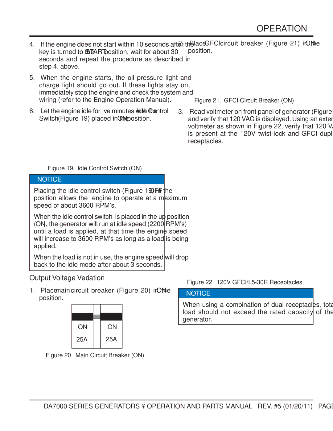
Output Voltage Verification
Place main circuit breaker in the on position
Emergency Shutdown
OPERATION/SHUTDOWN
Stopping the Engine Normal Shutdown
Generator Storage
Cover the generating set and store in a clean, dry place
Preparation for Long Term Storage
First Every
Maintenance
Engine Air Cleaner
Maintenance
Engine Oil
Oil Filter Cartridge
Replacing Fuel Filter Element
Cleaning the Fuel Filter
Radiator
Flushing Out Radiator and Replacing Coolant
Make sure engine coolant is at proper level
Radiator Cleaning
Generator Storage
Trailer Maintenance
Maintenance Trailer
Adjustable Channel
Wheel Hub Adjustment
Axle Bolt
Leaf Suspension
Trailer Towing Guidelines
Trailer Guidelines
Common Causes for Loss of Trailer
Coupling to the TOW Vehicle
Driving Conditions
Trailer VIN TAG
Inoperable BRAKES, Lights or Mirrors
Trailer Towing Tips
TOW Vehicle
Electrical Connector
Suspension System
Side View Mirrors
Jackstand
Safety Chains
Coupler Types
Ball Hitch Coupler
Coupling the Trailer to the Tow Vehicle Ball Coupler
Lock washer and hitch frame
Uncoupling the Ball Hitch
Attaching Safety Chain
Connecting Trailer Lights
Pintle Coupler and Pintle Hook
Pintle Hitch Coupler
Unsafe Tires, Lug Nuts or Wheels
Tire Safety
Step
Determining Load Limit of Trailer
Tighten lug nuts before each tow
Be sure lug nuts are tight before each tow
P indicates the tire is for passenger vehicles
Determining Load Limit of Tow Vehicle Step
Tire Fundamentals
Table A. Speed Rating
Replacing Worn or Damaged Tires
Tire Safety Tips
Tire Repair
Wheel Rims
Lights and Signals
Wheels, Bearings and Lug Nuts
Lug Nut Torque Requirements
Trailer Wiring Diagram
Trailer Wiring Digram
Generator Wiring Diagram DA7000 Series
Generator Wiring Digram
Engine Wiring Diagram
Engine Wiring Digram
Troubleshooting Engine and Generator
Bad Engine Installation? Repeat Installation of of Engine
Defective Wiring? Repair or Replace Wiring
Defective Idle Control Switch? Replace Idle Control Switch
Discharges too soon
Troubleshooting Engine
Bolt, glow plug and nozzle holder
Nut?
Page
Explanation of Code in Remarks Column
Sample Parts List
To 3 units
Suggested Spare Parts
30A
Nameplate and Decals Assy
Includes Items W/#
Decal Fuse BOX
Generator Assy
Rectifier Assy
Field Assy
FAN
KEY
Control Panel Assy
Indicator Assy
Idle Control Switch
Control Panel
AC VOLTMETER, 120/240
Electric Parts Assy
RESISTOR, 30W 10 OHM
Bracket Electric Parts
RECTIFIER, S5VB60
Relay
Engine and Radiator Assy
Hose AIR Cleaner
Bracket AIR Cleaner
Z482-E3B Engine
Engine Foot
Engine and Radiator Assy
Ring a P18
Plug
Hose Joint
Drain Hose
Battery Assy
Battery Sheet
Battery
Battery Band
Battery Bolt
Muffler Assy
HEX. Head Bolt
Muffler
Exhaust Pipe
Gasket
Fuel Tank Assy
CAP, Fuel Tank
Fuel Tank
Fuel Gauge
Tank Band
Whisperwatt
OIL Filter Retrofit Assy
Hose KIT
Adapter Filter
DA7000NUT
Lockwasher DA7000BOLT Bolt
Enclosure Assy
Bracket Radiator
Lining
FAN Shroud
Harness Guide
Enclosure Assy
Side Door
Roof PANEL, White Units
LINING, Orange Units
LINING, White Units
Rubber Seals Assy
0229400760
0229400470
0222900325
0222900125
Kubota Z482-EB/E2B/E3B Engine Crankcase Assy
CAP, Sealing
Crankcase Assy
PLUG, Expansion
PIN, Straight
Kubota Z482-EB/E2B/E3B Engine OIL Pump Assy
GASKET, OIL Pump NA
OIL Pump Assy
GEAR, OIL Pump Drive
KEY, Feather
Kubota Z482-EB/E2B/E3B Engine OIL PAN Assy
COMP. OIL PAN
OIL PAN Assy
PLUG, Drain
FILTER, OIL
Kubota Z482-EB/E2B/E3B ENG. Cylinder Head Assy
GUIDE, Inlet Valve
HOOK, Engine
GUIDE, Exhaust Valve
BOLT, Cylinder Head
Kubota Z482-EB/E2B/E3B Engine Gear Case Assy
PIN, Start Spring
Gear Case Assy
SEAL, OIL
Spring
Kubota Z482-EB/E2B/E3B Engine Head Cover Assy
JOINT, Breather Pipe
Head Cover ASSY. Z482-EB
PLATE, Breather Element
ELEMENT, Breather
Kubota Z482-EB/E2B/E3B Engine Head Cover Assy
PIPE, Water Return
Head Cover ASSY. Z482-E2B/Z482-E3B
COMP. Valve Breather
COVER, Breather
Kubota Z482-EB/E2B/E3B Engine OIL Filter Assy
JOINT, Pipe
OIL Filter Assy
Kubota Z482-EB/E2B/E3B ENG. Dipstick and Guide Assy
010 1685136410
Dipstick and Guide Assy
010 1G30436410
020 1745636420
Kubota Z482-EB/E2B/E3B ENG. Main Bearing Case Assy
METAL, Crankshaft M
Main Bearing Case Assy
BOLT, Bearing Case
GASKET, Bearing Case
Kubota Z482-EB/E2B/E3B Engine Camshaft and Idle Gear Assy
Push ROD
Camshaft and Idle Gear Shaft Assy
GEAR, CAM
STOPPER, Camshaft
Kubota Z482-EB/E2B/E3B ENG. Piston and Crankshaft Assy
Piston and Crankshaft Assy
BOLT, Connecting ROD
ASSY. Piston Ring STD
ASSY. Piston Ring +0.25MM
Kubota Z482-EB/E2B/E3B Engine Flywheel Assy
Flywheel Assy
HOUSING, Flywheel
GEAR, RING, Z482-EB
BOLT, Flywheel
Kubota Z482-EB/E2B/E3B ENG. Fuel Camshaft & GOV. Shaft Assy
CAMSHAFT, Fuel
Fuel Camshaft and Governor Shaft Assy
BEARING, Ball
GEAR, Injection Pump
Kubota Z482-EB/E2B/E3B ENG. ENG. Stop Lever Assy
CAP
Engine Stop Lever Assy
NUT, Lock
Z482-EB only
Kubota Z482-EB/E2B/E3B ENG. Stop Solenoid Assy
010 1685160013
010 1685160010
010 1685160014
020 0175450612
Kubota Z482-EB/E2B/E3B ENG. Injection Pump Assy
SHIM, Injection PUMP, 20 MM
Includes Items W/%
SHIM, Injection PUMP, 25 MM
SHIM, Injection PUMP, 30 MM
Kubota Z 482-EB ENGINE-INJECTION Pump Components Assy
PLUNGER, PUMP, Z482-EB
Injection Pump Components Assy
VALVE, Delivery
SPRING, DELIV. Valve
Kubota Z482-EB/E2B/E3B ENG. Speed Control Plate Assy
GASKET, Control Plate
Speed Control Plate Assy
LEVER, Speed Control
SPRING, Return
Kubota Z482-EB/E2B/E3B ENG. Nozzle Holder and Glow Assy
CORD, Glow Plug
Nozzle Holder and Glow Plug Assy
SEAL, Heat
Kubota Z482-EB/E2B/E3B Engine Nozzle Holder Assy
Part Name QTY Remarks
Kubota Z482-EB/E2B/E3B Engine Fork Lever Assy
SPRING, Start
Fork Lever Assy
SPRING, Governor
Includes ITEMS/#
Kubota Z482-EB/E2B/E3B Engine Fuel Filter Assy
LEVER, Cock
Includes Items W/$
SPRING, Valve
SCREW, SET
Kubota Z482-EB/E2B/E3B ENGINE-FUEL Pump Assy
010 1582152030
Fuel Pump Assy
020 1626452140
030 0102350616
Kubota Z482-EB/E2B/E3B Engine Dynamo & Pulley Assy
PULLEY, FAN Drive
Dynamo and Pulley Assy
STAY, Dynamo
Kubota Z482-EB/E2B/E3B Engine Dynamo Assy
Pulley
Dynamo Assy
SCREW, Round HD
Stator
Kubota Z482-EB/E2B/E3B Engine Starter Assy
010 1983763010
Starter Assy
Starter Assy V, 0.8KW
020 0112350825
Kubota Z482-EB/E2B/E3B Engine Starter COMP. Assy
WASHER, Adjusting
SWITCH, Magnetic
Starter Components Assy
LEVER, Drive
Kubota Z482-EB Engine OIL Switch Assy
010 1584139010
OIL Switch Assy
010 1584139013
020 1584196020
Kubota Z482-EB/E2B/E3B Engine Water Flange & THERM. Assy
BAND, Pipe
Water Flange and Thermostat Assy
Thermostat Assy
COVER, Thermostat
Kubota Z482-EB/E2B/E3B Engine Water Pump Assy
Includes Items W/@
Water Pump Assy
FLANGE, Water Pump
Bearing
Kubota Z482-EB/E2B/E3B Engine Water Pipe Assy
Water Pipe Assy
Kubota Z482-EB/E2B/E3B Engine FAN Assy
BOLT, Flange
FAN Assy
PULLEY, FAN
Kubota Z482-EB/E2B/E3B ENG. Valve and Rocker ARM Assy
Valve and Rocker ARM Assy
SCREW, Adjusting
VALVE, Inlet
VALVE, Exhaust
Kubota Z482-EB/E2B/E3B Engine Inlet Manifold Assy
GASKET, IN-MANIFOLD
Kubota Z482-EB/E2B/E3B Engine Exhaust Manifold Assy
MANIFOLD, Exhaust
Exhaust Manifold Assy
BOLT, UBS
NUT, UBS
Kubota Z482-EB/E2B/E3B ENG. Glow PLUG/LAMP and Timer Assy
010 1569465990
Glow PLUG/LAMP and Timer Assy
TIMER, Glow Lamp
Kubota Z482-EB/E2B/E3B Engine Starter Switch Assy
010 3741059110
CAP, Starter Switch
3741055180
6641655170
Kubota Z482-EB/E2B/E3B Engine AIR Cleaner Assy
BODY, AIR Cleaner
AIR Cleaner Assy
COVER, AIR Cleaner
BAND, AIR Cleaner
Kubota Z482-EB/E2B/E3B Engine Accessories
Emergency Unit
Accessories
Tube Fuel X13X400L
Tube Fuel X13X240L
Kubota Z482-EB/E2B/E3B Engine Piston KIT Option
010 1685321002
Piston KIT Option
Piston
ASSY. Piston Ring
Freight Policy
Terms and Conditions of Sale Parts
Page
HERE’S HOW to GET Help