MACHINE SETUP AND CALIBRATION
Set Zero Pitch Cylinder Stops
1.Flatten blades (bottom out the pitch cylinders).
2.Turn machine off.
3.Remove clevis pin (Item E, Figure 39) from pitch cylinder allowing yoke (Item B, Figure 39) to rest on thrust collar.
1.Turn machine off for at least 10 seconds and then restart machine.
2.Click “Calibration” button on machine setup page.
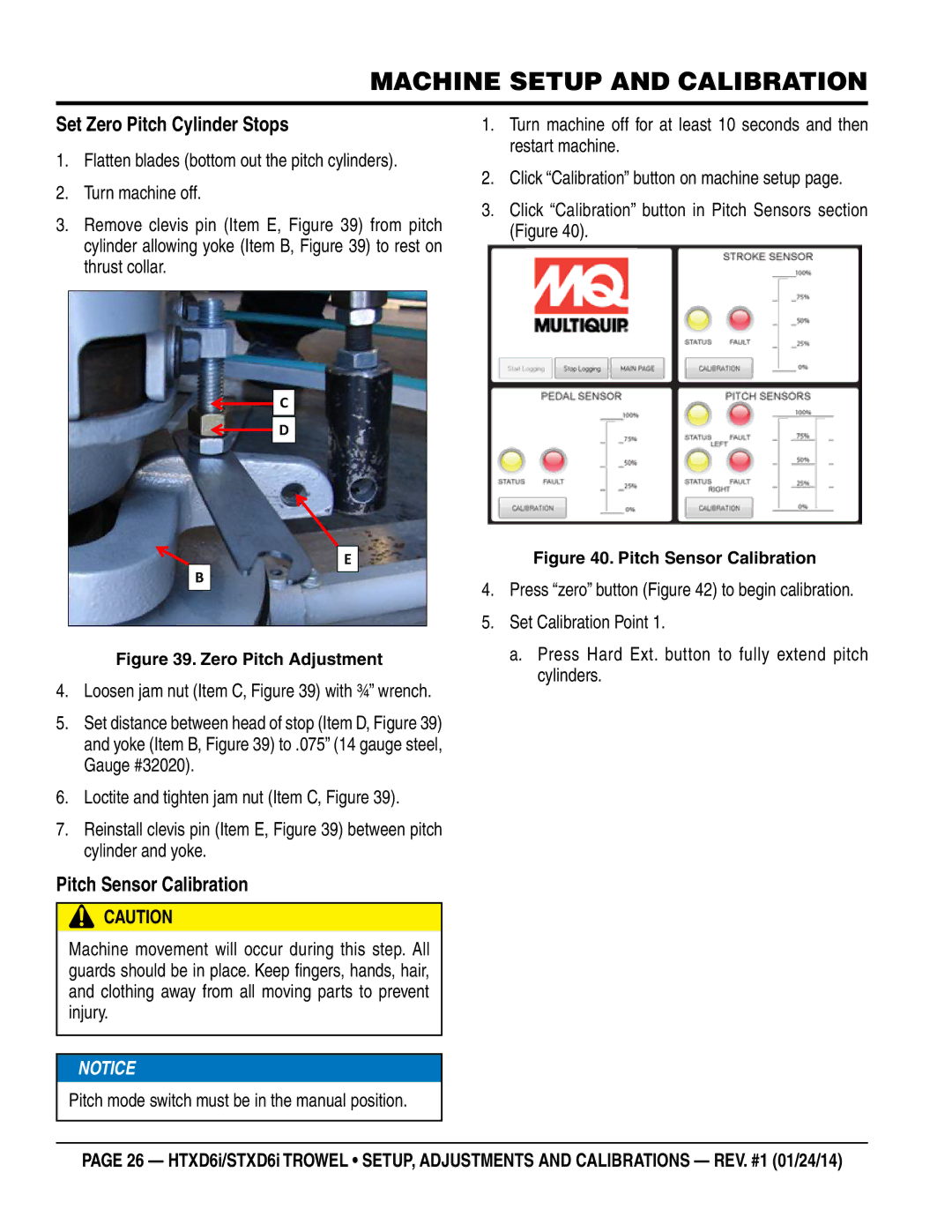
3.Click “Calibration” button in Pitch Sensors section (Figure 40).
![]() C
C
![]() D
D
E
B
Figure 39. Zero Pitch Adjustment
4.Loosen jam nut (Item C, Figure 39) with ¾” wrench.
5.Set distance between head of stop (Item D, Figure 39) and yoke (Item B, Figure 39) to .075” (14 gauge steel, Gauge #32020).
6.Loctite and tighten jam nut (Item C, Figure 39).
7.Reinstall clevis pin (Item E, Figure 39) between pitch cylinder and yoke.
Pitch Sensor Calibration
CAUTION
Machine movement will occur during this step. All guards should be in place. Keep fingers, hands, hair, and clothing away from all moving parts to prevent injury.
![]()
![]() NOTICE
NOTICE
Pitch mode switch must be in the manual position.
Figure 40. Pitch Sensor Calibration
4.Press “zero” button (Figure 42) to begin calibration.
5.Set Calibration Point 1.
a.Press Hard Ext. button to fully extend pitch cylinders.
PAGE 26 — HTXD6i/STXD6i TROWEL • SETUP, ADJUSTMENTS AND CALIBRATIONS — REV. #1 (01/24/14)