2400 ipx specifications
The NEC 2400 IPX is a robust and versatile business communication solution designed to meet the increasing demands of modern enterprises. It is a part of NEC's esteemed range of IP-based telephony systems, known for integrating sophisticated technology and user-friendly features.One of the main characteristics of the NEC 2400 IPX system is its modularity. This flexibility allows organizations to scale their communication needs effectively. The system can be customized with various modules that cater to specific requirements, enabling businesses to add or remove functions as their operations evolve. This adaptability makes the NEC 2400 IPX ideal for small to medium-sized enterprises as well as large organizations.
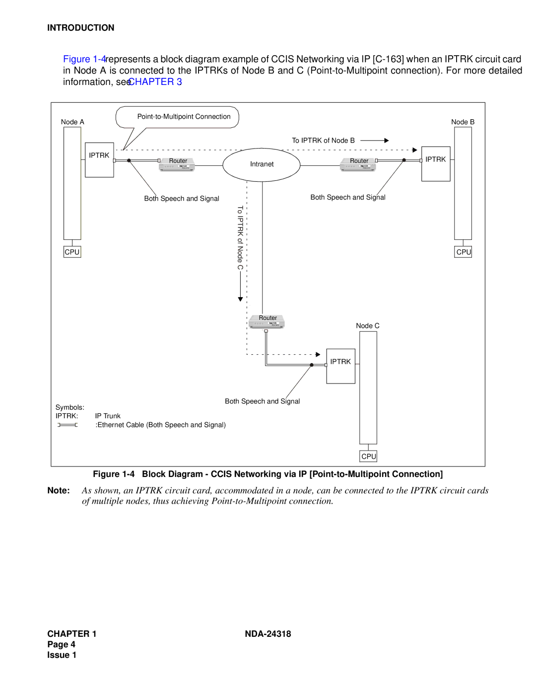
The NEC 2400 IPX incorporates advanced VoIP technology, which facilitates seamless communication over the internet. This leads to reduced operational costs, as traditional phone lines are no longer a necessity. VoIP also enhances mobility, allowing employees to stay connected irrespective of their physical location. The system supports a wide range of endpoints, including digital, analog, and IP phones, facilitating a diverse range of user preferences.
One of the standout features of the NEC 2400 IPX is its user-friendly interface. The system supports advanced call management functionalities, including call forwarding, conferencing, and voicemail services. This user-centric design ensures that businesses can streamline their communications efficiently while providing an intuitive experience for end users.
In addition to its communication capabilities, the NEC 2400 IPX integrates with various business applications, enhancing productivity and collaboration. The system supports features like presence management and instant messaging, allowing for real-time communication among team members. This integration strengthens teamwork and fosters a more connected workplace.
Moreover, the NEC 2400 IPX is built with security in mind. The system employs various encryption technologies to safeguard communications, ensuring that sensitive information remains protected against unauthorized access. This feature is particularly crucial for organizations in sectors such as finance and healthcare, where data security is paramount.
In summary, the NEC 2400 IPX is a leading telecommunications solution that combines modularity, VoIP technology, user-friendly features, and robust security measures. Its ability to adapt to the changing needs of businesses makes it a preferred choice for organizations looking to enhance their communication infrastructure. As technology continues to evolve, the NEC 2400 IPX stands out as a reliable and future-ready choice for modern enterprises.

