Ceiling Installation
|
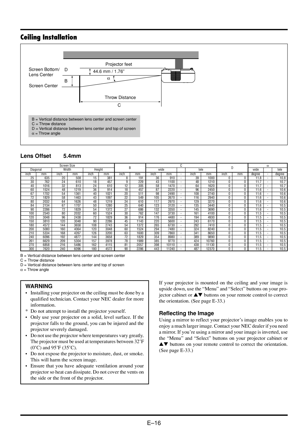
| Projector feet |
Screen Bottom/ | D | 44.6 mm / 1.76” |
Lens Center |
| |
| α | |
| B | |
Screen Center |
| |
|
| |
|
| Throw Distance |
|
| C |
B = Vertical distance between lens center and screen center
C = Throw distance
D = Vertical distance between lens center and top of screen
α= Throw angle
Lens Offset | 5.4mm |
|
|
|
|
|
|
|
|
|
|
|
|
|
|
|
|
|
|
| |||
|
|
|
|
|
|
|
|
|
|
|
|
|
|
|
|
|
|
|
|
|
|
| |
|
| Screen Size |
|
|
|
| B |
|
|
| C |
|
|
|
| D |
| α |
| ||||
Diagonal | Width |
| Height |
|
|
|
| wide |
|
| tele |
|
|
|
| wide |
| tele | |||||
inch | mm | inch |
| mm | inch |
| mm | inch |
| mm | inch |
| mm | - | inch |
| mm | inch |
| mm | degree | - | degree |
25 | 635 | 20 |
| 508 | 15 |
| 381 | 8 |
| 191 | 36 |
| 910 | - | 39 |
| 1000 | 0 |
| 0 | 11.8 | - | 10.8 |
30 | 762 | 24 |
| 610 | 18 |
| 457 | 9 |
| 229 | 43 |
| 1100 | - | 48 |
| 1210 | 0 |
| 0 | 11.7 | - | 10.7 |
40 | 1016 | 32 |
| 813 | 24 |
| 610 | 12 |
| 305 | 58 |
| 1470 | - | 64 |
| 1620 | 0 |
| 0 | 11.7 | - | 10.7 |
60 | 1524 | 48 |
| 1219 | 36 |
| 914 | 18 |
| 457 | 87 |
| 2220 | - | 96 |
| 2450 | 0 |
| 0 | 11.6 | - | 10.6 |
67 | 1702 | 54 |
| 1361 | 40 |
| 1021 | 20 |
| 511 | 98 |
| 2490 | - | 108 |
| 2740 | 0 |
| 0 | 11.6 | - | 10.6 |
72 | 1829 | 58 |
| 1463 | 43 |
| 1097 | 22 |
| 549 | 105 |
| 2670 | - | 116 |
| 2940 | 0 |
| 0 | 11.6 | - | 10.6 |
80 | 2032 | 64 |
| 1626 | 48 |
| 1219 | 24 |
| 610 | 117 |
| 2970 | - | 129 |
| 3270 | 0 |
| 0 | 11.6 | - | 10.6 |
84 | 2134 | 67 |
| 1707 | 50 |
| 1280 | 25 |
| 640 | 123 |
| 3120 | - | 135 |
| 3440 | 0 |
| 0 | 11.6 | - | 10.5 |
90 | 2286 | 72 |
| 1829 | 54 |
| 1372 | 27 |
| 686 | 132 |
| 3350 | - | 145 |
| 3690 | 0 |
| 0 | 11.6 | - | 10.5 |
100 | 2540 | 80 |
| 2032 | 60 |
| 1524 | 30 |
| 762 | 147 |
| 3730 | - | 161 |
| 4100 | 0 |
| 0 | 11.5 | - | 10.5 |
120 | 3048 | 96 |
| 2438 | 72 |
| 1829 | 36 |
| 914 | 176 |
| 4480 | - | 194 |
| 4930 | 0 |
| 0 | 11.5 | - | 10.5 |
150 | 3810 | 120 |
| 3048 | 90 |
| 2286 | 45 |
| 1143 | 220 |
| 5600 | - | 243 |
| 6170 | 0 |
| 0 | 11.5 | - | 10.5 |
180 | 4572 | 144 |
| 3658 | 108 |
| 2743 | 54 |
| 1372 | 265 |
| 6730 | - | 292 |
| 7410 | 0 |
| 0 | 11.5 | - | 10.5 |
200 | 5080 | 160 |
| 4064 | 120 |
| 3048 | 60 |
| 1524 | 294 |
| 7480 | - | 324 |
| 8240 | 0 |
| 0 | 11.5 | - | 10.5 |
210 | 5334 | 168 |
| 4267 | 126 |
| 3200 | 63 |
| 1600 | 309 |
| 7860 | - | 341 |
| 8650 | 0 |
| 0 | 11.5 | - | 10.5 |
240 | 6096 | 192 |
| 4877 | 144 |
| 3658 | 72 |
| 1829 | 354 |
| 8980 | - | 389 |
| 9890 | 0 |
| 0 | 11.5 | - | 10.5 |
261 | 6629 | 209 |
| 5304 | 157 |
| 3978 | 78 |
| 1989 | 385 |
| 9770 | - | 424 |
| 10760 | 0 |
| 0 | 11.5 | - | 10.5 |
270 | 6858 | 216 |
| 5486 | 162 |
| 4115 | 81 |
| 2057 | 398 |
| 10110 | - | 438 |
| 11130 | 0 |
| 0 | 11.5 | - | 10.5 |
300 | 7620 | 240 |
| 6096 | 180 |
| 4572 | 90 |
| 2286 | 443 |
| 11240 | - | 487 |
| 12370 | 0 |
| 0 | 11.5 | - | 10.5 |
B = Vertical distance between lens center and screen center
C = Throw distance
D = Vertical distance between lens center and top of screen
α= Throw angle
WARNING
•Installing your projector on the ceiling must be done by a qualified technician. Contact your NEC dealer for more information.
* Do not attempt to install the projector yourself.
•Only use your projector on a solid, level surface. If the projector falls to the ground, you can be injured and the projector severely damaged.
•Do not use the projector where temperatures vary greatly. The projector must be used at temperatures between 32˚F (0˚C) and 95˚F (35˚C).
•Do not expose the projector to moisture, dust, or smoke. This will harm the screen image.
•Ensure that you have adequate ventilation around your projector so heat can dissipate. Do not cover the vents on the side or the front of the projector.
If your projector is mounted on the ceiling and your image is upside down, use the “Menu” and “Select” buttons on your pro- jector cabinet or ▲▼ buttons on your remote control to correct the orientation. (See page
Reflecting the Image
Using a mirror to reflect your projector’s image enables you to enjoy a much larger image. Contact your NEC dealer if you need a mirror. If you’re using a mirror and your image is inverted, use the “Menu” and “Select” buttons on your projector cabinet or ▲▼ buttons on your remote control to correct the orientation. (See page