Understanding LED Indicators
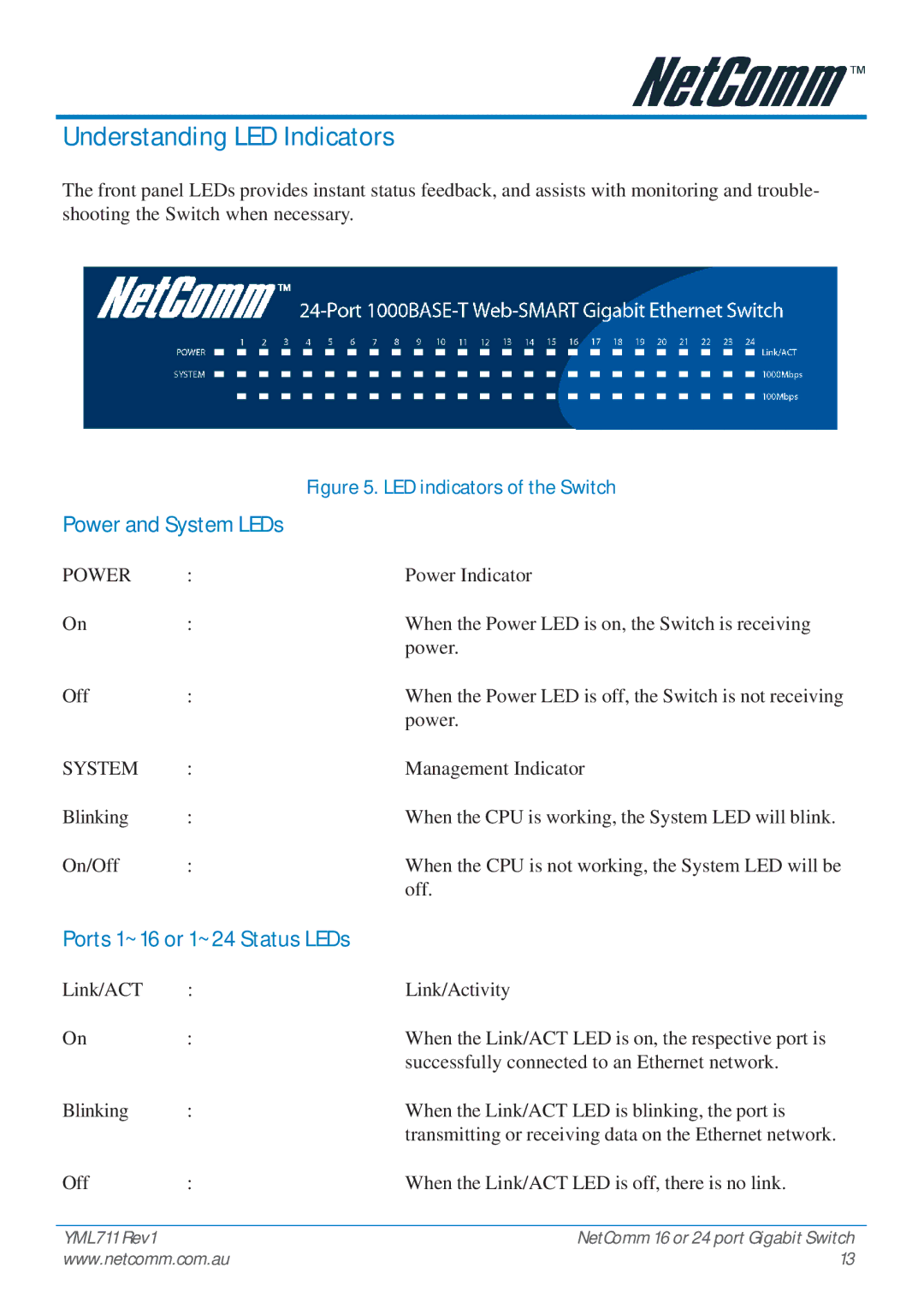
The front panel LEDs provides instant status feedback, and assists with monitoring and trouble- shooting the Switch when necessary.
|
| Figure 5. LED indicators of the Switch |
Power and System LEDs |
| |
POWER | : | Power Indicator |
On | : | When the Power LED is on, the Switch is receiving |
|
| power. |
Off | : | When the Power LED is off, the Switch is not receiving |
|
| power. |
SYSTEM | : | Management Indicator |
Blinking | : | When the CPU is working, the System LED will blink. |
On/Off | : | When the CPU is not working, the System LED will be |
|
| off. |
Ports 1~16 or 1~24 Status LEDs | ||
Link/ACT | : | Link/Activity |
On | : | When the Link/ACT LED is on, the respective port is |
|
| successfully connected to an Ethernet network. |
Blinking | : | When the Link/ACT LED is blinking, the port is |
|
| transmitting or receiving data on the Ethernet network. |
Off | : | When the Link/ACT LED is off, there is no link. |
YML711 Rev1 | NetComm 16 or 24 port Gigabit Switch |
www.netcomm.com.au | 13 |
