NTI AUDIO/HD VIDEO MATRIX SWITCH
Command Protocol
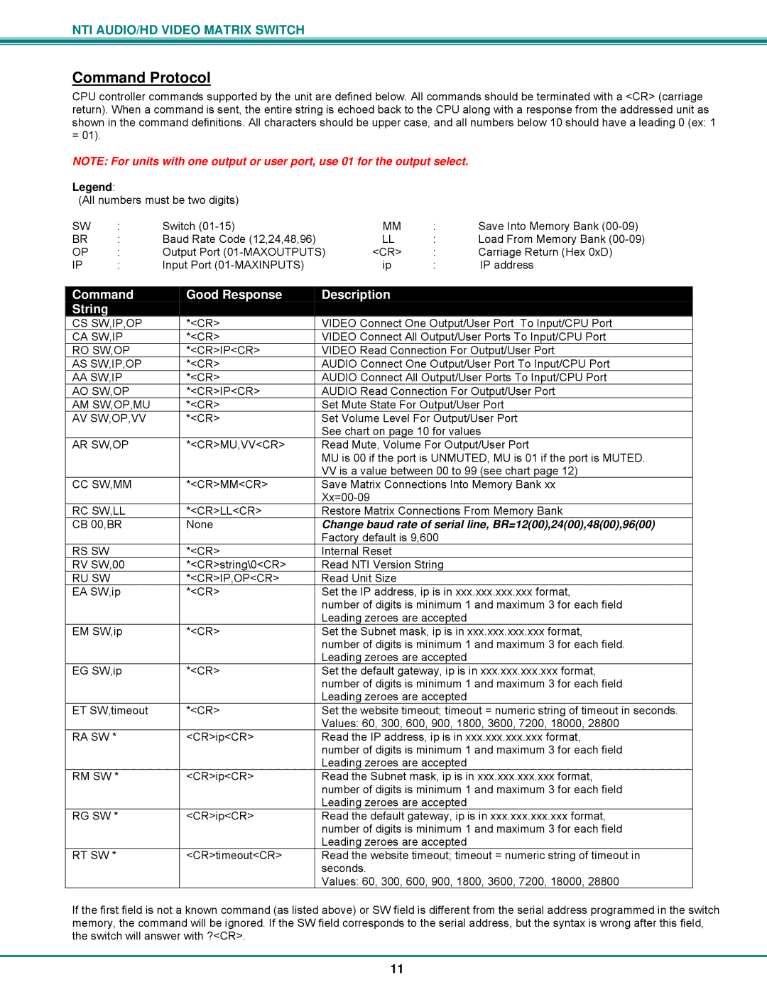
CPU controller commands supported by the unit are defined below. All commands should be terminated with a <CR> (carriage return). When a command is sent, the entire string is echoed back to the CPU along with a response from the addressed unit as shown in the command definitions. All characters should be upper case, and all numbers below 10 should have a leading 0 (ex: 1 = 01).
NOTE: For units with one output or user port, use 01 for the output select.
Legend:
(All numbers must be two digits)
SW | : | Switch | MM | : | Save Into Memory Bank |
BR | : | Baud Rate Code (12,24,48,96) | LL | : | Load From Memory Bank |
OP | : | Output Port | <CR> | : | Carriage Return (Hex 0xD) |
IP | : | Input Port | ip | : | IP address |
Command | Good Response | Description | |
String |
|
| |
CS SW,IP,OP | *<CR> | VIDEO Connect One Output/User Port To Input/CPU Port | |
CA SW,IP | *<CR> | VIDEO Connect All Output/User Ports To Input/CPU Port | |
RO SW,OP | *<CR>IP<CR> | VIDEO Read Connection For Output/User Port | |
AS SW,IP,OP | *<CR> | AUDIO Connect One Output/User Port To Input/CPU Port | |
AA SW,IP | *<CR> | AUDIO Connect All Output/User Ports To Input/CPU Port | |
AO SW,OP | *<CR>IP<CR> | AUDIO Read Connection For Output/User Port | |
AM SW,OP,MU | *<CR> | Set Mute State For Output/User Port | |
AV SW,OP,VV | *<CR> | Set Volume Level For Output/User Port | |
|
| See chart on page 10 for values | |
AR SW,OP | *<CR>MU,VV<CR> | Read Mute, Volume For Output/User Port | |
|
| MU is 00 if the port is UNMUTED, MU is 01 if the port is MUTED. | |
|
| VV is a value between 00 to 99 (see chart page 12) | |
CC SW,MM | *<CR>MM<CR> | Save Matrix Connections Into Memory Bank xx | |
|
| ||
RC SW,LL | *<CR>LL<CR> | Restore Matrix Connections From Memory Bank | |
CB 00,BR | None | Change baud rate of serial line, BR=12(00),24(00),48(00),96(00) | |
|
| Factory default is 9,600 | |
RS SW | *<CR> | Internal Reset | |
RV SW,00 | *<CR>string\0<CR> | Read NTI Version String | |
RU SW | *<CR>IP,OP<CR> | Read Unit Size | |
EA SW,ip | *<CR> | Set the IP address, ip is in xxx.xxx.xxx.xxx format, | |
|
| number of digits is minimum 1 and maximum 3 for each field | |
|
| Leading zeroes are accepted | |
EM SW,ip | *<CR> | Set the Subnet mask, ip is in xxx.xxx.xxx.xxx format, | |
|
| number of digits is minimum 1 and maximum 3 for each field. | |
|
| Leading zeroes are accepted | |
EG SW,ip | *<CR> | Set the default gateway, ip is in xxx.xxx.xxx.xxx format, | |
|
| number of digits is minimum 1 and maximum 3 for each field | |
|
| Leading zeroes are accepted | |
ET SW,timeout | *<CR> | Set the website timeout; timeout = numeric string of timeout in seconds. | |
|
| Values: 60, 300, 600, 900, 1800, 3600, 7200, 18000, 28800 | |
RA SW * | <CR>ip<CR> | Read the IP address, ip is in xxx.xxx.xxx.xxx format, | |
|
| number of digits is minimum 1 and maximum 3 for each field | |
|
| Leading zeroes are accepted | |
RM SW * | <CR>ip<CR> | Read the Subnet mask, ip is in xxx.xxx.xxx.xxx format, | |
|
| number of digits is minimum 1 and maximum 3 for each field | |
|
| Leading zeroes are accepted | |
RG SW * | <CR>ip<CR> | Read the default gateway, ip is in xxx.xxx.xxx.xxx format, | |
|
| number of digits is minimum 1 and maximum 3 for each field | |
|
| Leading zeroes are accepted | |
RT SW * | <CR>timeout<CR> | Read the website timeout; timeout = numeric string of timeout in | |
|
| seconds. | |
|
| Values: 60, 300, 600, 900, 1800, 3600, 7200, 18000, 28800 |
If the first field is not a known command (as listed above) or SW field is different from the serial address programmed in the switch memory, the command will be ignored. If the SW field corresponds to the serial address, but the syntax is wrong after this field, the switch will answer with ?<CR>.
11
