MODEL 85 INSTALLATION OF CLOSE CLEARANCE SHIELDS
(Optional)
1.Loosen the three (3) phillips head screws that secure the front cover plates to the front sides of the stove.
2.Take rear close clearance shield and center with back and flushing with the bottom of the stove using the
2.Remove
3.You must measure one inch (1”) out from the side of the stove to the inside of the shield and main- tain approximately one inch (1”) clearance while securing the shield to the back of the stove with the
4.Before tightening the screws, insert the front end (Lip) of the side shield under the front cover plate on the front side of the stove. Use the same step to install side shield on the op- posite side of the stove.
5.Tighten all screws.
6.Place pipe shield on the back of the rear shield and align the two (2) holes on the parts and secure with the phillips head screws provided.
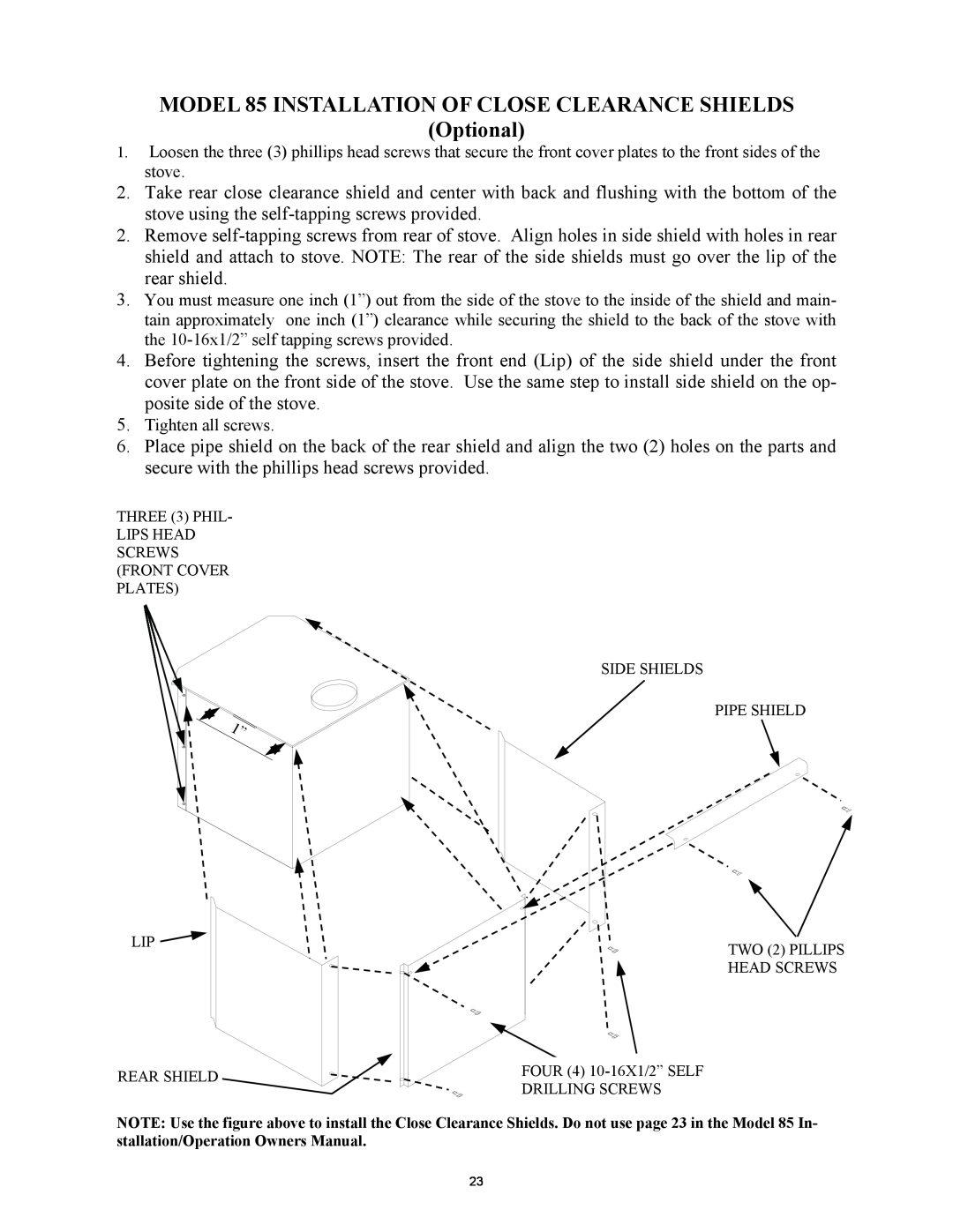
THREE (3) PHIL-
LIPS HEAD SCREWS (FRONT COVER PLATES)
SIDE SHIELDS
PIPE SHIELD
LIP ![]()
TWO (2) PILLIPS HEAD SCREWS
REAR SHIELD
FOUR (4)
NOTE: Use the figure above to install the Close Clearance Shields. Do not use page 23 in the Model 85 In- stallation/Operation Owners Manual.
23