 LCD panel
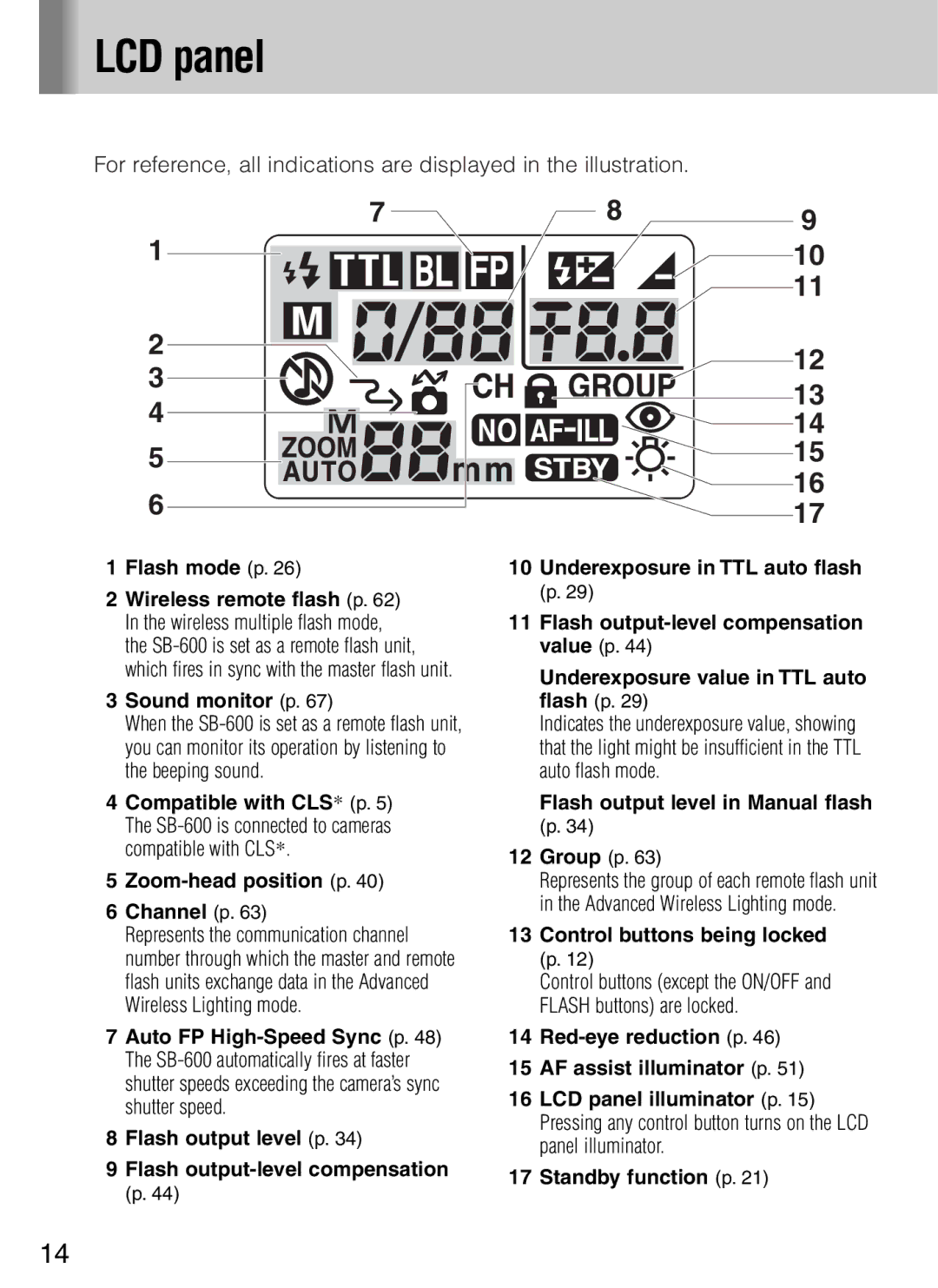
For reference, all indications are displayed in the illustration.
7
1
2
3
4
5
6
1Flash mode (p. 26)
2Wireless remote flash (p. 62) In the wireless multiple flash mode, the
3Sound monitor (p. 67)
When the
4Compatible with CLS* (p. 5) The
5Zoom-head position (p. 40)
6Channel (p. 63)
Represents the communication channel number through which the master and remote flash units exchange data in the Advanced Wireless Lighting mode.
7Auto FP
8Flash output level (p. 34)
9Flash
89  10
10 
 11
11
12
13
14
15
16
17
10Underexposure in TTL auto flash (p. 29)
11Flash
Underexposure value in TTL auto flash (p. 29)
Indicates the underexposure value, showing that the light might be insufficient in the TTL auto flash mode.
Flash output level in Manual flash (p. 34)
12Group (p. 63)
Represents the group of each remote flash unit in the Advanced Wireless Lighting mode.
13Control buttons being locked (p. 12)
Control buttons (except the ON/OFF and FLASH buttons) are locked.
14
15AF assist illuminator (p. 51)
16LCD panel illuminator (p. 15) Pressing any control button turns on the LCD panel illuminator.
17Standby function (p. 21)
14
