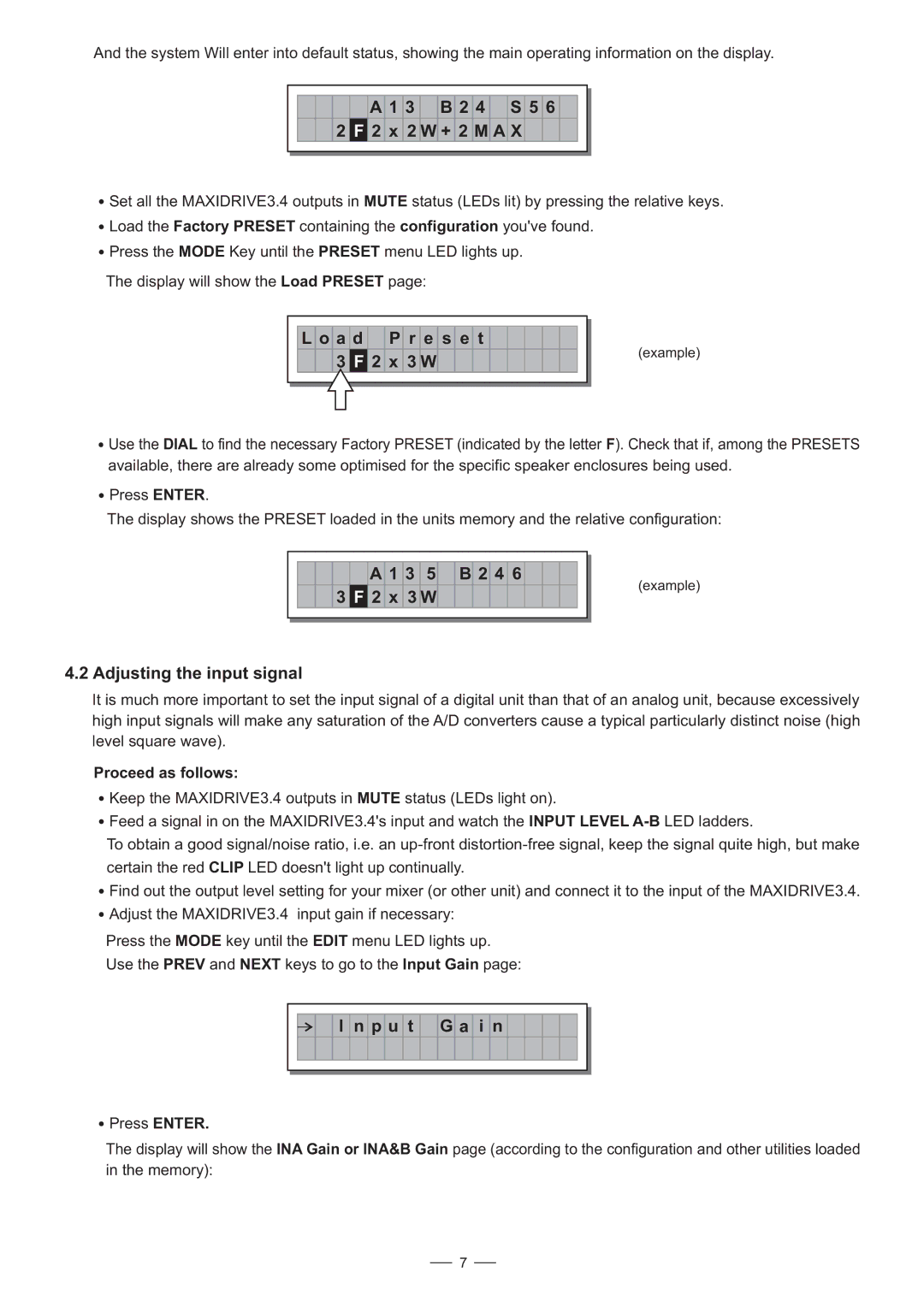
And the system Will enter into default status, showing the main operating information on the display.
A 1 3 B 2 4 S 5 6
2F 2 x 2 W + 2 M A X
![]() Set all the MAXIDRIVE3.4 outputs in MUTE status (LEDs lit) by pressing the relative keys.
Set all the MAXIDRIVE3.4 outputs in MUTE status (LEDs lit) by pressing the relative keys.
![]() Load the Factory PRESET containing the configuration you've found.
Load the Factory PRESET containing the configuration you've found.
![]() Press the MODE Key until the PRESET menu LED lights up.
Press the MODE Key until the PRESET menu LED lights up.
The display will show the Load PRESET page:
L o a d P r e s e t
3 F 2 x 3 W
(example)
![]() Use the DIAL to find the necessary Factory PRESET (indicated by the letter F). Check that if, among the PRESETS available, there are already some optimised for the specific speaker enclosures being used.
Use the DIAL to find the necessary Factory PRESET (indicated by the letter F). Check that if, among the PRESETS available, there are already some optimised for the specific speaker enclosures being used.
![]() Press ENTER.
Press ENTER.
The display shows the PRESET loaded in the units memory and the relative configuration:
A 1 3 5 B 2 4 6
3 F 2 x 3 W
4.2 Adjusting the input signal
(example)
It is much more important to set the input signal of a digital unit than that of an analog unit, because excessively high input signals will make any saturation of the A/D converters cause a typical particularly distinct noise (high level square wave).
Proceed as follows:
![]() Keep the MAXIDRIVE3.4 outputs in MUTE status (LEDs light on).
Keep the MAXIDRIVE3.4 outputs in MUTE status (LEDs light on).
![]() Feed a signal in on the MAXIDRIVE3.4's input and watch the INPUT LEVEL
Feed a signal in on the MAXIDRIVE3.4's input and watch the INPUT LEVEL
To obtain a good signal/noise ratio, i.e. an
![]() Find out the output level setting for your mixer (or other unit) and connect it to the input of the MAXIDRIVE3.4.
Find out the output level setting for your mixer (or other unit) and connect it to the input of the MAXIDRIVE3.4.
![]() Adjust the MAXIDRIVE3.4 input gain if necessary:
Adjust the MAXIDRIVE3.4 input gain if necessary:
Press the MODE key until the EDIT menu LED lights up.
Use the PREV and NEXT keys to go to the Input Gain page:
I n p u t
G a i n
![]() Press ENTER.
Press ENTER.
The display will show the INA Gain or INA&B Gain page (according to the configuration and other utilities loaded in the memory):
7