Numbers 1, 2, 3, 4, 5 and 6 indicate the respective outputs.
In the example:
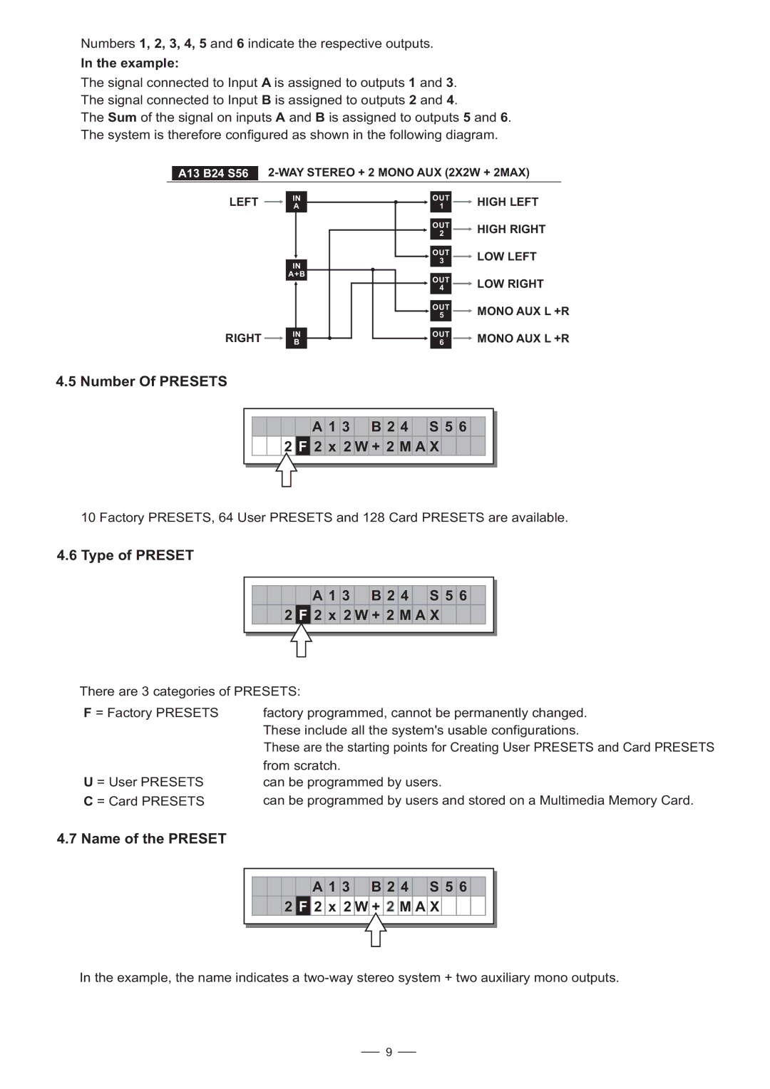
The signal connected to Input A is assigned to outputs 1 and 3. The signal connected to Input B is assigned to outputs 2 and 4.
The Sum of the signal on inputs A and B is assigned to outputs 5 and 6. The system is therefore configured as shown in the following diagram.
A13 B24 S56
LEFT |
|
| IN |
|
| A | |
|
|
| |
|
|
|
|
IN
A+B
RIGHT |
|
| IN |
|
| B | |
|
|
|
|
OUT |
|
| HIGH LEFT |
1 |
|
| |
|
|
| |
|
|
| |
OUT |
|
| HIGH RIGHT |
2 |
|
| |
|
|
| |
|
|
| |
OUT |
|
| LOW LEFT |
3 |
|
| |
|
|
| |
OUT |
|
| LOW RIGHT |
4 |
|
| |
|
|
| |
|
|
| |
OUT |
|
| MONO AUX L +R |
5 |
|
| |
|
|
| |
OUT |
|
| MONO AUX L +R |
6 |
|
| |
|
|
|
|
4.5 Number Of PRESETS
A 1 3 B 2 4 S 5 6
2 F 2 x 2 W + 2 M A X
10 Factory PRESETS, 64 User PRESETS and 128 Card PRESETS are available.
4.6 Type of PRESET
A 1 3 B 2 4 S 5 6
2F 2 x 2 W + 2 M A X
There are 3 categories of PRESETS:
F = Factory PRESETS | factory programmed, cannot be permanently changed. |
| These include all the system's usable configurations. |
| These are the starting points for Creating User PRESETS and Card PRESETS |
| from scratch. |
U = User PRESETS | can be programmed by users. |
C = Card PRESETS | can be programmed by users and stored on a Multimedia Memory Card. |
4.7 Name of the PRESET
A 1 3 B 2 4 S 5 6
2 F 2 x 2 W + 2 M A X
In the example, the name indicates a
9