1.INTRODUCTION
Your MAXIDRIVE3.4 is a
2.FEATURES
![]() Single rack unit
Single rack unit
![]() Delay lines up to 2.5s for each input and up to 300ms for each output
Delay lines up to 2.5s for each input and up to 300ms for each output
![]() Stereo digital input in AEX/EBU format
Stereo digital input in AEX/EBU format
![]() A/D and D/A converters for a 117dB dynamic range
A/D and D/A converters for a 117dB dynamic range
![]() Slot for a memory card for the storage of more presets and an easier upgrade of other units
Slot for a memory card for the storage of more presets and an easier upgrade of other units
![]() 10 Factory presets, 64 user presets and 128 card presets by large memory capacity
10 Factory presets, 64 user presets and 128 card presets by large memory capacity
![]() Switching power supply
Switching power supply
![]() Remote control
Remote control
![]() manufactured under QS9000, VDA6.1 certified management system
manufactured under QS9000, VDA6.1 certified management system
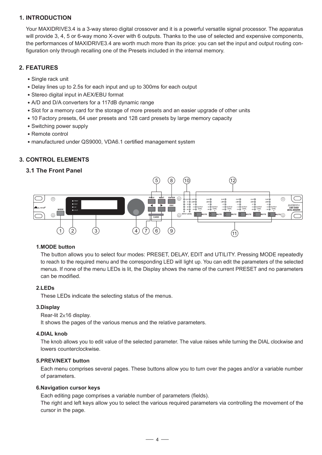
3.CONTROL ELEMENTS 3.1 The Front Panel
5 | 8 | 10 | 12 |
| PREV | NEXT | ENTER |
|
|
|
|
|
|
|
|
|
|
|
|
|
|
|
|
| CLIP | CLIP |
| CLIP |
| CLIP |
| CLIP |
| CLIP |
| CLIP |
|
| PRESET |
|
| 6 | LIMIT |
| LIMIT |
| LIMIT |
| LIMIT |
| LIMIT |
| LIMIT |
|
|
|
|
|
|
|
|
|
|
| |||||||
| DELAY |
| ESC | 12 | 6 |
| 6 |
| 6 |
| 6 |
| 6 |
| 6 |
|
|
|
| 18 | 12 | OUTPUT | 12 | OUTPUT | 12 | OUTPUT | 12 | OUTPUT | 12 | OUTPUT | 12 | OUTPUT | |
LTOR | EDIT |
|
| |||||||||||||
MODE | UTILITY |
|
| 24 | 24 | LEVEL | 24 | LEVEL | 24 | LEVEL | 24 | LEVEL | 24 | LEVEL | 24 | LEVEL |
|
|
|
| A | B | 1 |
| 2 |
| 3 |
| 4 |
| 5 |
| 6 |
|
|
|
|
|
|
|
|
|
|
|
|
|
|
| ||
|
|
|
| INPUT LEVEL | MUTE | MUTE | MUTE | MUTE | MUTE | MUTE | ||||||
|
|
|
|
|
| |||||||||||
| CARD |
|
|
|
|
|
|
|
|
|
|
|
|
|
|
|
DIGITAL CROSSOVER
1 | 2 | 3 | 4 | 7 | 6 | 9 | 11 |
|
|
|
|
|
|
|
1.MODE button
The button allows you to select four modes: PRESET, DELAY, EDIT and UTILITY. Pressing MODE repeatedly to reach to the required menu and the corresponding LED will light up. You can edit the parameters of the selected menus. If none of the menu LEDs is lit, the Display shows the name of the current PRESET and no parameters can be modified.
2.LEDs
These LEDs indicate the selecting status of the menus.
3.Display
![]() 16 display.
16 display.
It shows the pages of the various menus and the relative parameters.
4.DIAL knob
The knob allows you to edit value of the selected parameter. The value raises while turning the DIAL clockwise and lowers counterclockwise.
5.PREV/NEXT button
Each menu comprises several pages. These buttons allow you to turn over the pages and/or a variable number of parameters.
6.Navigation cursor keys
Each editing page comprises a variable number of parameters (fields).
The right and left keys allow you to select the various required parameters via controlling the movement of the cursor in the page.
4
