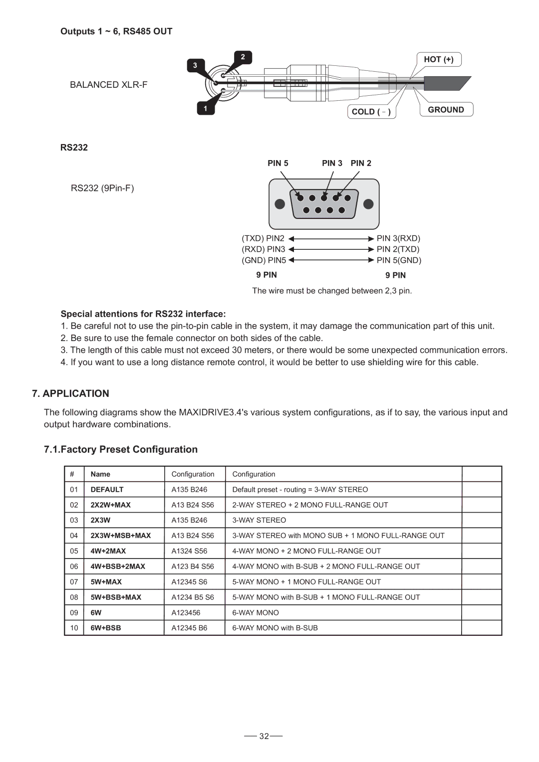
Outputs 1 ~ 6, RS485 OUT
2 | HOT (+) |
|
3
BALANCED
1 |
|
|
| GROUND | |
COLD ( | ) | ||||
|
| ||||
RS232
PIN 5 | PIN 3 PIN 2 |
RS232 (9Pin-F)
(TXD) PIN2 ![]()
![]() PIN 3(RXD)
PIN 3(RXD)
(RXD) PIN3 ![]()
![]() PIN 2(TXD)
PIN 2(TXD)
(GND) PIN5 ![]()
![]() PIN 5(GND)
PIN 5(GND)
9 PIN | 9 PIN |
The wire must be changed between 2,3 pin.
Special attentions for RS232 interface:
1.Be careful not to use the
2.Be sure to use the female connector on both sides of the cable.
3.The length of this cable must not exceed 30 meters, or there would be some unexpected communication errors.
4.If you want to use a long distance remote control, it would be better to use shielding wire for this cable.
7.APPLICATION
The following diagrams show the MAXIDRIVE3.4's various system configurations, as if to say, the various input and output hardware combinations.
7.1.Factory Preset Configuration
# | Name | Configuration | Configuration |
01 | DEFAULT | A135 B246 | Default preset - routing = |
02 | 2X2W+MAX | A13 B24 S56 | |
03 | 2X3W | A135 B246 | |
04 | 2X3W+MSB+MAX | A13 B24 S56 | |
05 | 4W+2MAX | A1324 S56 | |
06 | 4W+BSB+2MAX | A123 B4 S56 | |
07 | 5W+MAX | A12345 S6 | |
08 | 5W+BSB+MAX | A1234 B5 S6 | |
09 | 6W | A123456 | |
10 | 6W+BSB | A12345 B6 | |
|
|
|
|
32