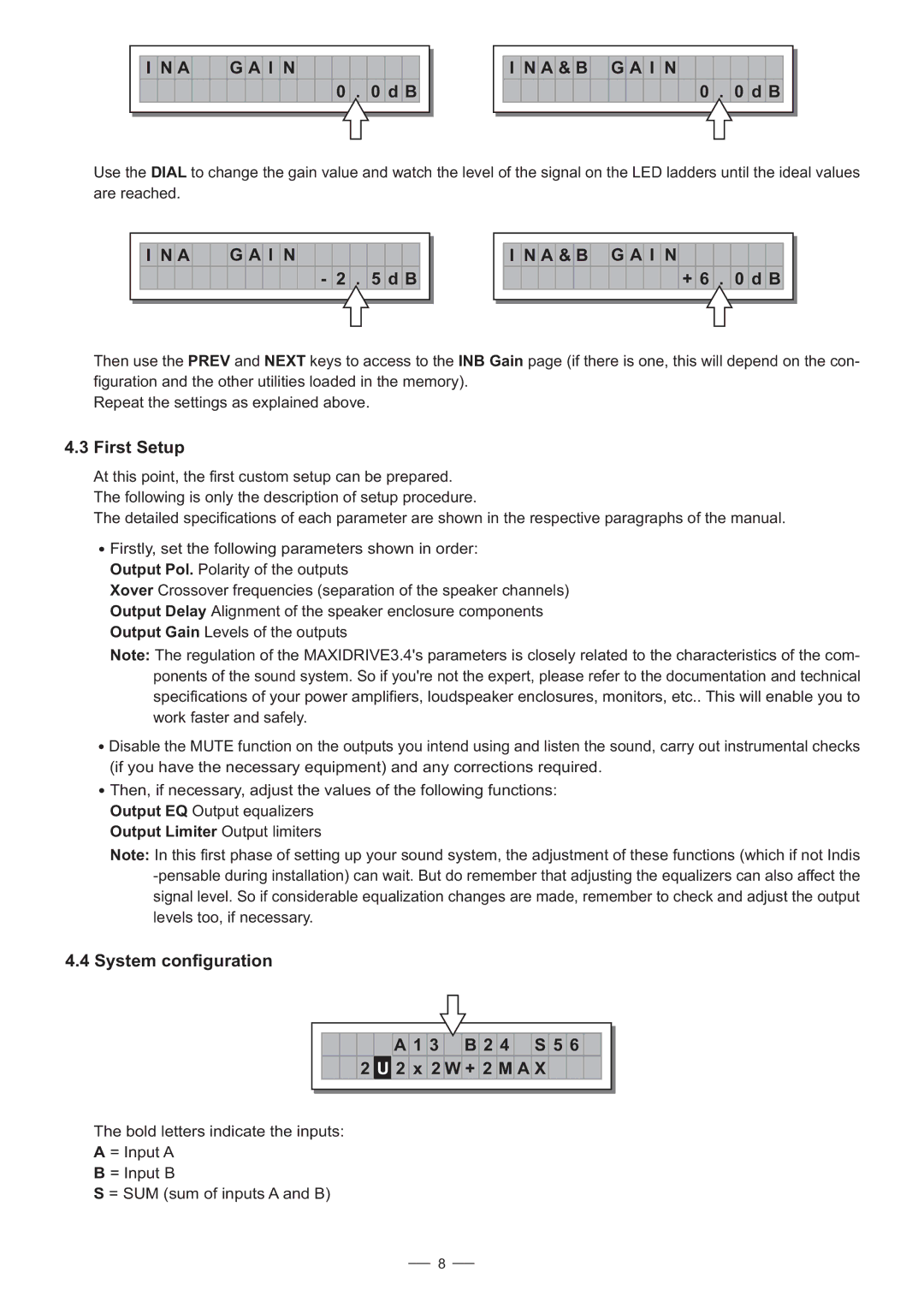
I N A G A I N
0 . 0 d B
I N A & B G A I N
0 . 0 d B
Use the DIAL to change the gain value and watch the level of the signal on the LED ladders until the ideal values are reached.
I N A G A I N
- 2 . 5 d B
I N A & B G A I N
+ 6 . 0 d B
Then use the PREV and NEXT keys to access to the INB Gain page (if there is one, this will depend on the con- figuration and the other utilities loaded in the memory).
Repeat the settings as explained above.
4.3First Setup
At this point, the first custom setup can be prepared. The following is only the description of setup procedure.
The detailed specifications of each parameter are shown in the respective paragraphs of the manual.
![]() Firstly, set the following parameters shown in order:
Firstly, set the following parameters shown in order:
Output Pol. Polarity of the outputs
Xover Crossover frequencies (separation of the speaker channels)
Output Delay Alignment of the speaker enclosure components
Output Gain Levels of the outputs
Note: The regulation of the MAXIDRIVE3.4's parameters is closely related to the characteristics of the com- ponents of the sound system. So if you're not the expert, please refer to the documentation and technical specifications of your power amplifiers, loudspeaker enclosures, monitors, etc.. This will enable you to work faster and safely.
![]() Disable the MUTE function on the outputs you intend using and listen the sound, carry out instrumental checks (if you have the necessary equipment) and any corrections required.
Disable the MUTE function on the outputs you intend using and listen the sound, carry out instrumental checks (if you have the necessary equipment) and any corrections required.
![]() Then, if necessary, adjust the values of the following functions:
Then, if necessary, adjust the values of the following functions:
Output EQ Output equalizers
Output Limiter Output limiters
Note: In this first phase of setting up your sound system, the adjustment of these functions (which if not Indis
4.4 System configuration
A 1 3 B 2 4 S 5 6
2 U 2 x 2 W + 2 M A X
The bold letters indicate the inputs:
A = Input A
B = Input B
S = SUM (sum of inputs A and B)
8