7.Memory Card Slot
The Slot allows you to insert the Memory Card which is very useful for safe storage of PRESETS and for their transfer from one MAXIDRIVE3.4 to another.
8.ENTER key
The key allows you to access to the selected editing page. Pressing this key, you can edit and confirm the required value of parameter.
9.ESC key
The key allows you to exit the selected editing page. It also used to reject the value to enter and return to the stored value.
10.Input Level LEDs
The LEDs are used to indicate the level of input A/B. In order to get an
11.Mute switches
There are six mute switches
12.Output Level LEDs
These LEDs indicate the level of the respective outputs (you can adjust the output via adjusting the Output Gain parameter of Edit menu.)
Note: The LIMITER on any output will change the way in which the level is displayed on the corresponding LED. In fact, the level shown on the ladder is no longer the "absolute" output level, but the level of the signal at
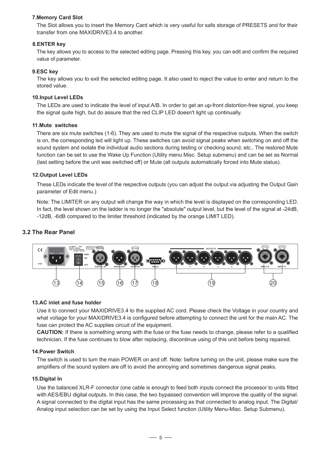
3.2 The Rear Panel
A102
AC INPUT 14W | Apparaten skall anslutas till |
|
|
|
|
|
|
|
|
| ||
jordat uttag nar den ansluts |
| PUSH |
|
|
|
|
|
| ||||
FUSE: | till ett natverk | PUSH |
|
|
|
|
| OUTPUTS |
| |||
|
|
|
|
|
|
|
|
|
|
|
| |
PWR |
|
|
|
|
|
|
|
|
|
|
| |
|
| NEW | TIDE |
| NEW | TIDE |
|
|
|
|
|
|
ON |
| 3 |
| 3 |
|
|
|
|
|
|
| |
|
| 2 | 1 |
| 2 | 1 |
|
|
|
|
|
|
OFF |
|
|
|
|
|
|
|
|
|
|
| |
|
| DIGITAL IN | RS485 OUT | RS485 IN | RS232 | 6 | 5 | 4 | 3 | 2 | ||
| PUSH | PUSH | ||
| NEW | TIDE | NEW | TIDE |
| 2 | 1 | 2 | 1 |
|
| 3 |
| 3 |
1 | INPUT B | INPUT A | ||
13 | 14 | 15 | 16 | 17 | 18 | 19 | 20 |
13.AC inlet and fuse holder
Use it to connect your MAXIDRIVE3.4 to the supplied AC cord. Please check the Voltage in your country and what voltage for your MAXIDRIVE3.4 is configured before attempting to connect the unit for the main AC. The fuse can protect the AC supplies circuit of the equipment.
CAUTION: If there is something wrong with the fuse or the fuse needs to change, please refer to a qualified technician. If the fuse continues to blow after replacing, discontinue using of this unit before being repaired.
14.Power Switch
The switch is used to turn the main POWER on and off. Note: before turning on the unit, please make sure the amplifiers of the sound system are off to avoid the annoying and sometimes dangerous signal peaks.
15.Digital In
Use the balanced
5