(ATC 1 and ATC 2) are combined through one phasing transformer (located at ATC 2) and then connected to Duplexer position 2 and the main TX/RX Antenna. The output of the upper ATC (ATC 3) is connected to Duplexer position 3 and the diversity TX/RX Antenna. This arrangement is used to meet the requirement of a minimum of 21 channel spacing (630 kHz) between the channels in one RF Frame. This configuration requires a TX/RX antenna to perform the diversity receive function of the cell. See Figure
Control Channel redundancy
Control Channel (CCH) redundancy is commonly provided with a Locate Channel Receiver (LCR) backup. The CCH is assigned to position 1 on the TRU/DPA Shelf 1 and the LCR is assigned to position 4 on the same shelf. This arrangement will have the CCH and the LCR supplied on a different DC power feed and a TCM card. No RF coaxial switch is required since the cavity of the LCR position on the ATC will tune to the CCH frequency when backup is required.
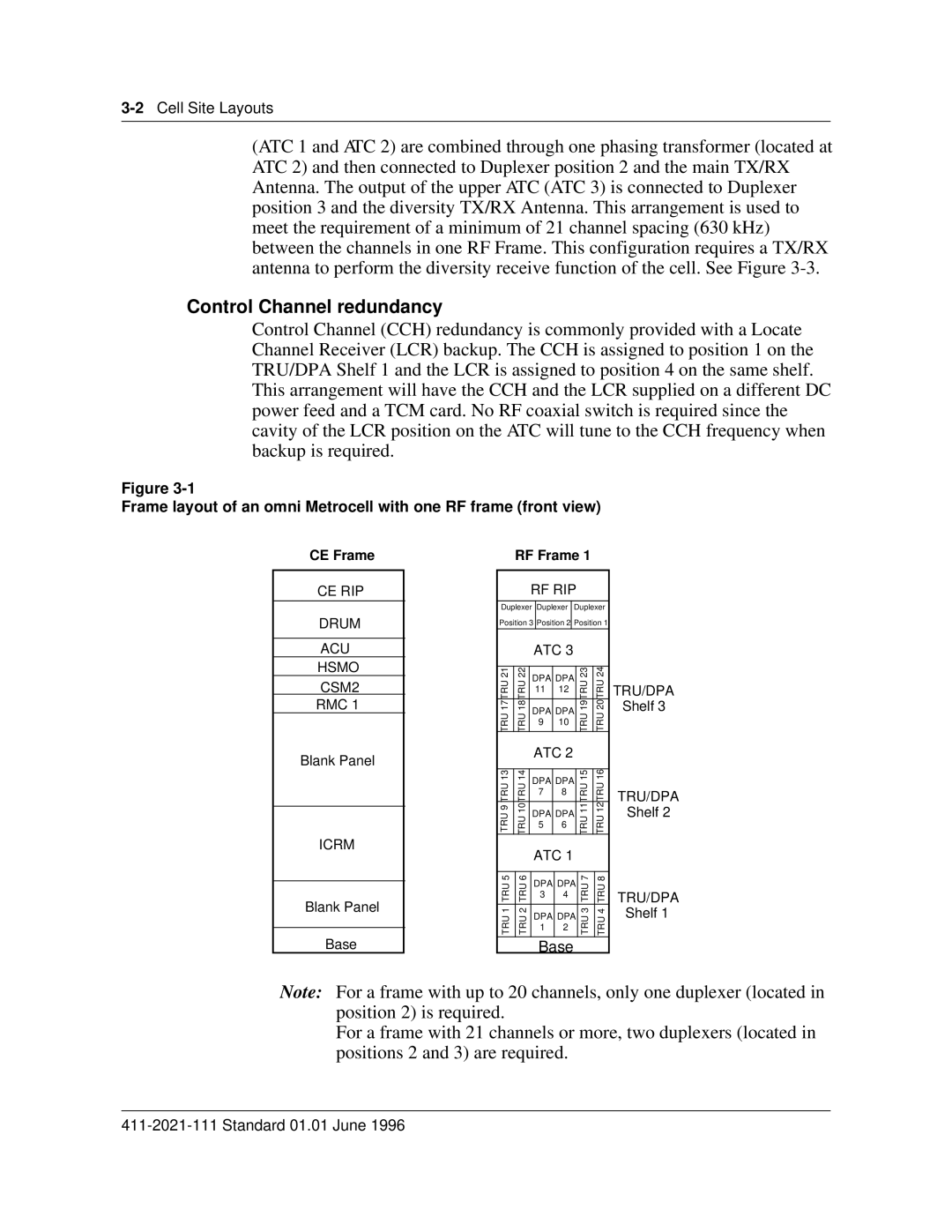
Figure
Frame layout of an omni Metrocell with one RF frame (front view)
CE Frame
CE RIP
DRUM
ACU
HSMO
CSM2
RMC 1
Blank Panel
ICRM
Blank Panel
Base
RF Frame 1
RF RIP
Duplexer Duplexer Duplexer
Position 3 Position 2 Position 1
|
| ATC 3 |
|
|
| |||
|
|
|
|
|
|
|
| |
21 | 22 | DPA | DPA | 23 | 24 |
| ||
17TRU | 18TRU | 19TRU | 20TRU | TRU/DPA | ||||
11 |
| 12 | ||||||
|
|
|
|
| ||||
TRU | TRU | DPA | DPA | TRU | TRU | Shelf 3 | ||
9 |
| 10 |
| |||||
|
|
|
|
|
| |||
|
|
|
|
|
|
|
| |
|
| ATC 2 |
|
|
| |||
|
|
|
|
|
|
|
| |
13 | 14 | DPA | DPA | 15 | 16 |
| ||
TRU9TRU | 10TRUTRU | 11TRUTRU | 12TRUTRU |
| ||||
7 |
| 8 | TRU/DPA | |||||
|
|
|
|
| ||||
|
|
|
|
|
|
| ||
|
| DPA | DPA |
|
| Shelf 2 | ||
|
| 5 |
| 6 |
|
|
| |
|
|
|
|
|
|
|
| |
|
| ATC 1 |
|
|
| |||
|
|
|
|
|
|
|
| |
5 | 6 | DPA | DPA | 7 | 8 |
| ||
TRU | TRU | TRU | TRU | TRU/DPA | ||||
3 |
| 4 | ||||||
|
|
|
|
|
| |||
|
|
|
|
|
|
| Shelf 1 | |
1 | 2 | DPA | DPA | 3 | 4 | |||
TRU | TRU | 1 |
| 2 | TRU | TRU |
| |
|
|
|
|
|
| |||
|
|
|
|
|
|
|
| |
Base
Note: For a frame with up to 20 channels, only one duplexer (located in position 2) is required.
For a frame with 21 channels or more, two duplexers (located in positions 2 and 3) are required.