3-12 Cell Site Layouts
Transmit cabling
In the transmit path, the output of each Transmit Receive Unit (TRU) is connected to the input of each corresponding power amplifier (PA) on the Dual Power Amplifier (DPA) module.
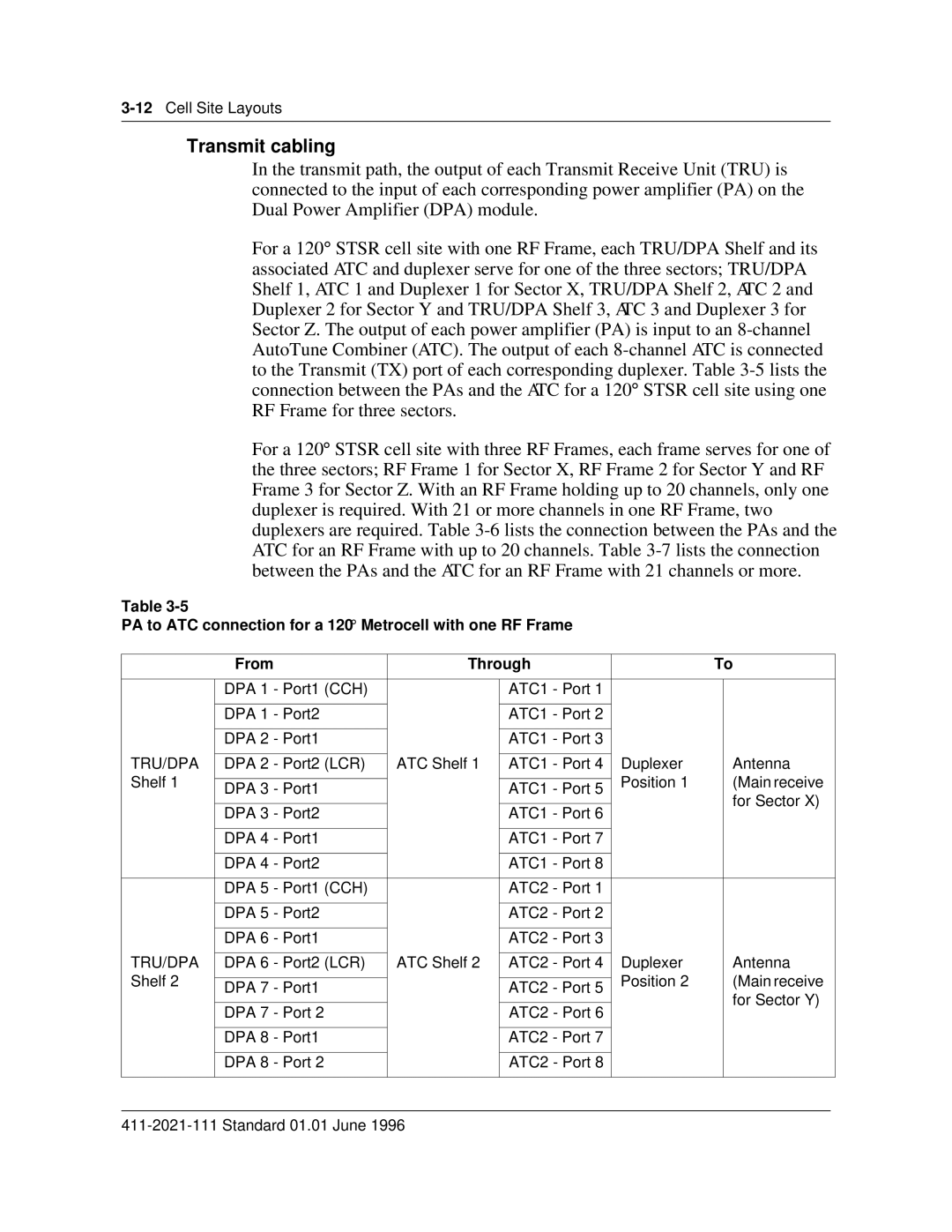
For a 120° STSR cell site with one RF Frame, each TRU/DPA Shelf and its associated ATC and duplexer serve for one of the three sectors; TRU/DPA Shelf 1, ATC 1 and Duplexer 1 for Sector X, TRU/DPA Shelf 2, ATC 2 and Duplexer 2 for Sector Y and TRU/DPA Shelf 3, ATC 3 and Duplexer 3 for Sector Z. The output of each power amplifier (PA) is input to an
For a 120° STSR cell site with three RF Frames, each frame serves for one of the three sectors; RF Frame 1 for Sector X, RF Frame 2 for Sector Y and RF Frame 3 for Sector Z. With an RF Frame holding up to 20 channels, only one duplexer is required. With 21 or more channels in one RF Frame, two duplexers are required. Table
Table
PA to ATC connection for a 120° Metrocell with one RF Frame
| From | Through |
| To | ||
|
|
|
|
|
|
|
| DPA 1 - Port1 (CCH) |
| ATC1 - Port 1 |
|
|
|
|
|
|
|
|
|
|
| DPA 1 - Port2 |
| ATC1 - Port 2 |
|
|
|
|
|
|
|
|
|
|
| DPA 2 - Port1 |
| ATC1 - Port 3 |
|
|
|
|
|
|
|
|
|
|
TRU/DPA | DPA 2 - Port2 (LCR) | ATC Shelf 1 | ATC1 - Port 4 | Duplexer |
| Antenna |
Shelf 1 |
|
|
| Position 1 |
| (Main receive |
DPA 3 - Port1 |
| ATC1 - Port 5 |
| |||
|
|
|
| for Sector X) | ||
|
|
|
|
|
| |
| DPA 3 - Port2 |
| ATC1 - Port 6 |
|
| |
|
|
|
|
| ||
|
|
|
|
|
|
|
| DPA 4 - Port1 |
| ATC1 - Port 7 |
|
|
|
|
|
|
|
|
|
|
| DPA 4 - Port2 |
| ATC1 - Port 8 |
|
|
|
|
|
|
|
|
|
|
| DPA 5 - Port1 (CCH) |
| ATC2 - Port 1 |
|
|
|
|
|
|
|
|
|
|
| DPA 5 - Port2 |
| ATC2 - Port 2 |
|
|
|
|
|
|
|
|
|
|
| DPA 6 - Port1 |
| ATC2 - Port 3 |
|
|
|
|
|
|
|
|
|
|
TRU/DPA | DPA 6 - Port2 (LCR) | ATC Shelf 2 | ATC2 - Port 4 | Duplexer |
| Antenna |
Shelf 2 |
|
|
| Position 2 |
| (Main receive |
DPA 7 - Port1 |
| ATC2 - Port 5 |
| |||
|
|
|
| for Sector Y) | ||
|
|
|
|
|
| |
| DPA 7 - Port 2 |
| ATC2 - Port 6 |
|
| |
|
|
|
|
| ||
|
|
|
|
|
|
|
| DPA 8 - Port1 |
| ATC2 - Port 7 |
|
|
|
|
|
|
|
|
|
|
| DPA 8 - Port 2 |
| ATC2 - Port 8 |
|
|
|
|
|
|
|
|
|
|
