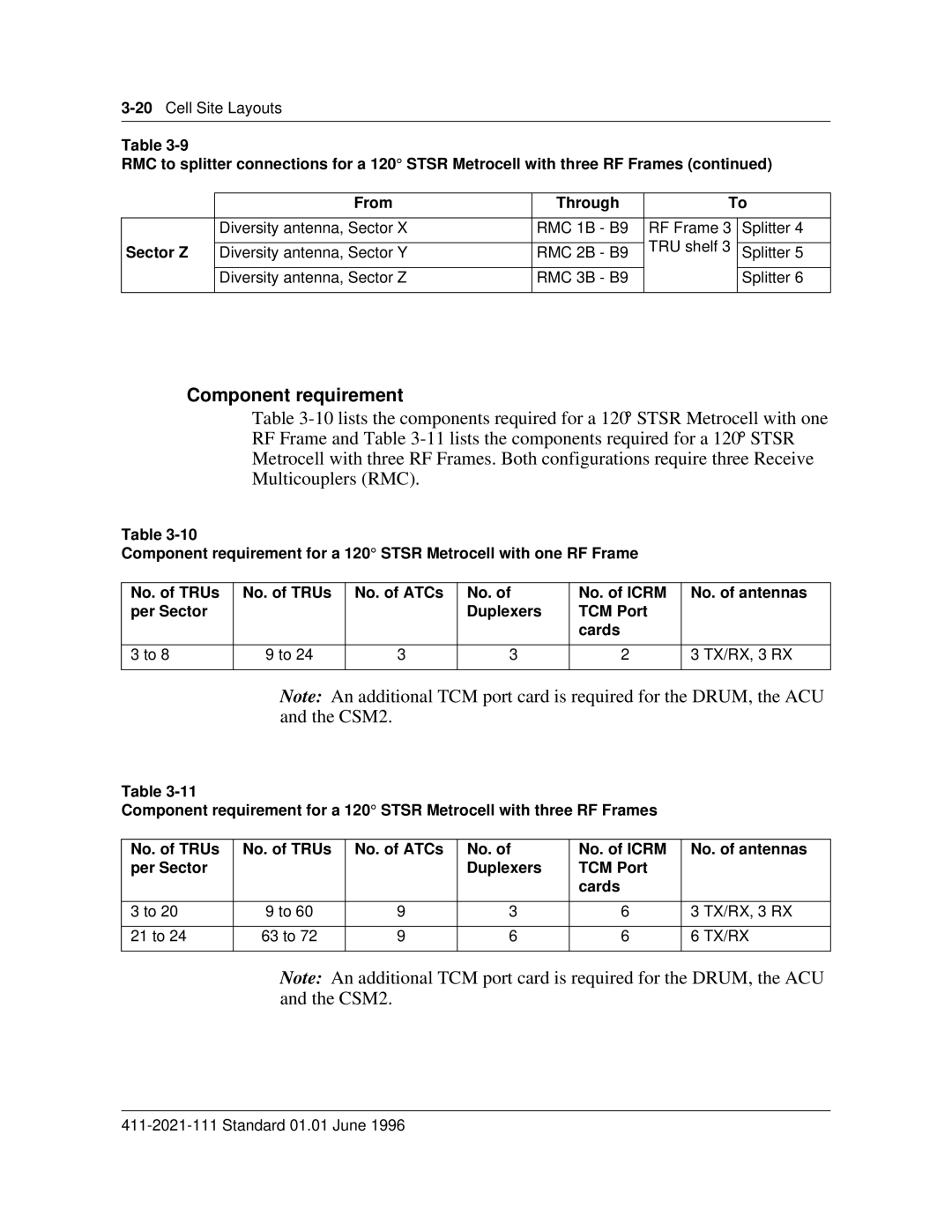
Table
RMC to splitter connections for a 120° STSR Metrocell with three RF Frames (continued)
| From | Through | To | |
|
|
|
|
|
| Diversity antenna, Sector X | RMC 1B - B9 | RF Frame 3 | Splitter 4 |
Sector Z |
|
| TRU shelf 3 |
|
Diversity antenna, Sector Y | RMC 2B - B9 | Splitter 5 | ||
|
|
|
|
|
| Diversity antenna, Sector Z | RMC 3B - B9 |
| Splitter 6 |
|
|
|
|
|
Component requirement
Table
Table
Component requirement for a 120° STSR Metrocell with one RF Frame
No. of TRUs | No. of TRUs | No. of ATCs | No. of | No. of ICRM | No. of antennas |
per Sector |
|
| Duplexers | TCM Port |
|
|
|
|
| cards |
|
|
|
|
|
|
|
3 to 8 | 9 to 24 | 3 | 3 | 2 | 3 TX/RX, 3 RX |
|
|
|
|
|
|
Note: An additional TCM port card is required for the DRUM, the ACU and the CSM2.
Table
Component requirement for a 120° STSR Metrocell with three RF Frames
No. of TRUs | No. of TRUs | No. of ATCs | No. of | No. of ICRM | No. of antennas | |
per Sector |
|
| Duplexers | TCM Port |
|
|
|
|
|
| cards |
|
|
|
|
|
|
|
|
|
3 to 20 | 9 to 60 | 9 | 3 | 6 | 3 | TX/RX, 3 RX |
|
|
|
|
|
|
|
21 to 24 | 63 to 72 | 9 | 6 | 6 | 6 | TX/RX |
|
|
|
|
|
|
|
Note: An additional TCM port card is required for the DRUM, the ACU and the CSM2.
