Nortel Networks 411-2021-111 manual List of tables

Models: 411-2021-111

1 98
Download 98 pages 40.1 Kb
Page 7
Image 7

Contents vii

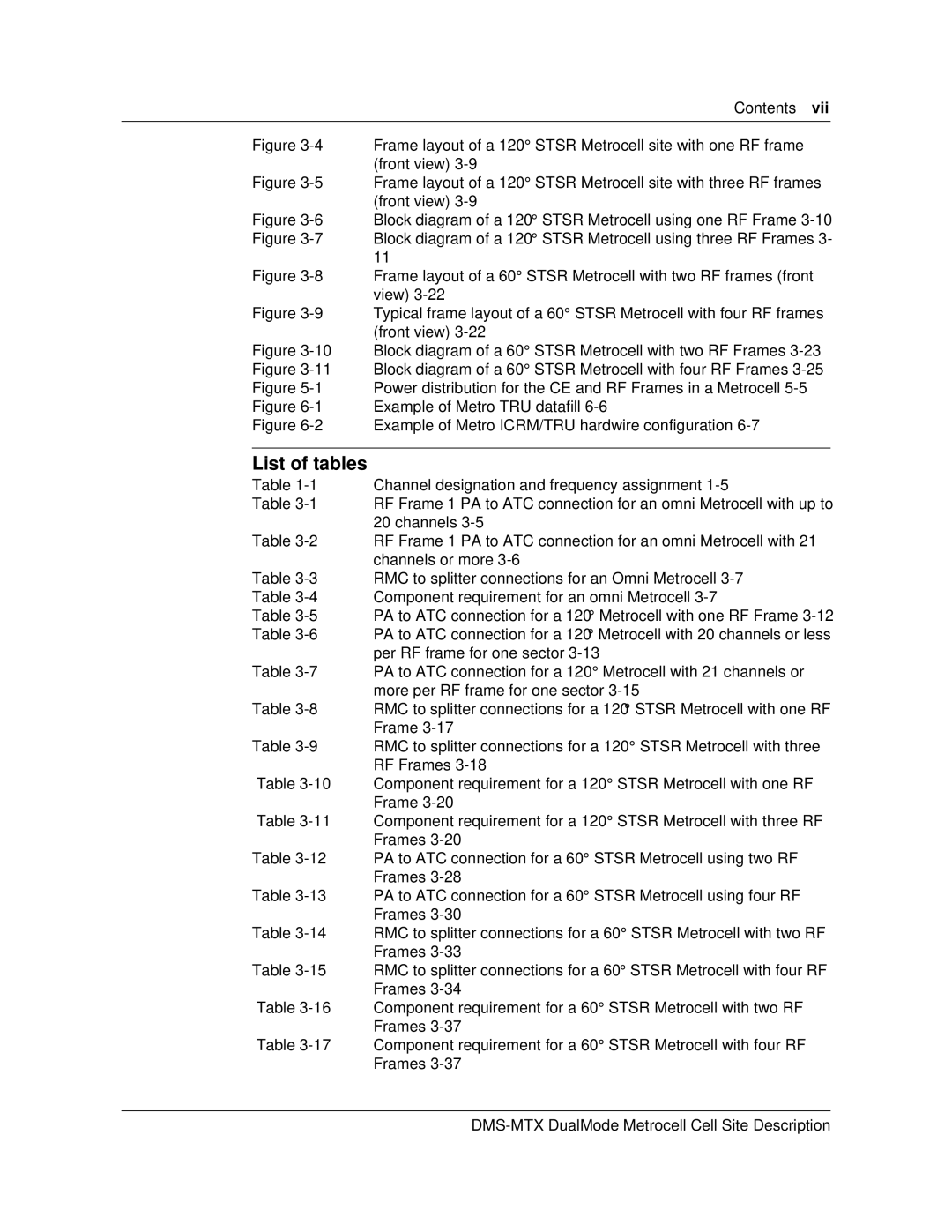
Figure 3-4 Frame layout of a 120° STSR Metrocell site with one RF frame (front view) 3-9

Figure 3-5 Frame layout of a 120° STSR Metrocell site with three RF frames (front view) 3-9

Figure 3-6 Block diagram of a 120° STSR Metrocell using one RF Frame 3-10

Figure 3-7 Block diagram of a 120° STSR Metrocell using three RF Frames 3- 11

Figure 3-8 Frame layout of a 60° STSR Metrocell with two RF frames (front view) 3-22

Figure 3-9 Typical frame layout of a 60° STSR Metrocell with four RF frames (front view) 3-22

Figure 3-10 Block diagram of a 60° STSR Metrocell with two RF Frames 3-23

Figure 3-11 Block diagram of a 60° STSR Metrocell with four RF Frames 3-25

Figure 5-1 Power distribution for the CE and RF Frames in a Metrocell 5-5

Figure 6-1 Example of Metro TRU datafill 6-6

Figure 6-2 Example of Metro ICRM/TRU hardwire configuration 6-7

List of tables

Table 1-1 Channel designation and frequency assignment 1-5

Table 3-1 RF Frame 1 PA to ATC connection for an omni Metrocell with up to 20 channels 3-5

Table 3-2 RF Frame 1 PA to ATC connection for an omni Metrocell with 21 channels or more 3-6

Table 3-3 RMC to splitter connections for an Omni Metrocell 3-7

Table 3-4 Component requirement for an omni Metrocell 3-7

Table 3-5 PA to ATC connection for a 120° Metrocell with one RF Frame 3-12

Table 3-6 PA to ATC connection for a 120° Metrocell with 20 channels or less per RF frame for one sector 3-13

Table 3-7 PA to ATC connection for a 120° Metrocell with 21 channels or more per RF frame for one sector 3-15

Table 3-8 RMC to splitter connections for a 120° STSR Metrocell with one RF Frame 3-17

Table 3-9 RMC to splitter connections for a 120° STSR Metrocell with three RF Frames 3-18

Table 3-10 Component requirement for a 120° STSR Metrocell with one RF Frame 3-20

Table 3-11 Component requirement for a 120° STSR Metrocell with three RF Frames 3-20

Table 3-12 PA to ATC connection for a 60° STSR Metrocell using two RF Frames 3-28

Table 3-13 PA to ATC connection for a 60° STSR Metrocell using four RF Frames 3-30

Table 3-14 RMC to splitter connections for a 60° STSR Metrocell with two RF Frames 3-33

Table 3-15 RMC to splitter connections for a 60° STSR Metrocell with four RF Frames 3-34

Table 3-16 Component requirement for a 60° STSR Metrocell with two RF Frames 3-37

Table 3-17 Component requirement for a 60° STSR Metrocell with four RF Frames 3-37

DMS-MTX DualMode Metrocell Cell Site Description

Page 7
Image 7
Nortel Networks 411-2021-111 manual List of tables, Block diagram of a 120 Stsr Metrocell using one RF Frame