3-22 Cell Site Layouts
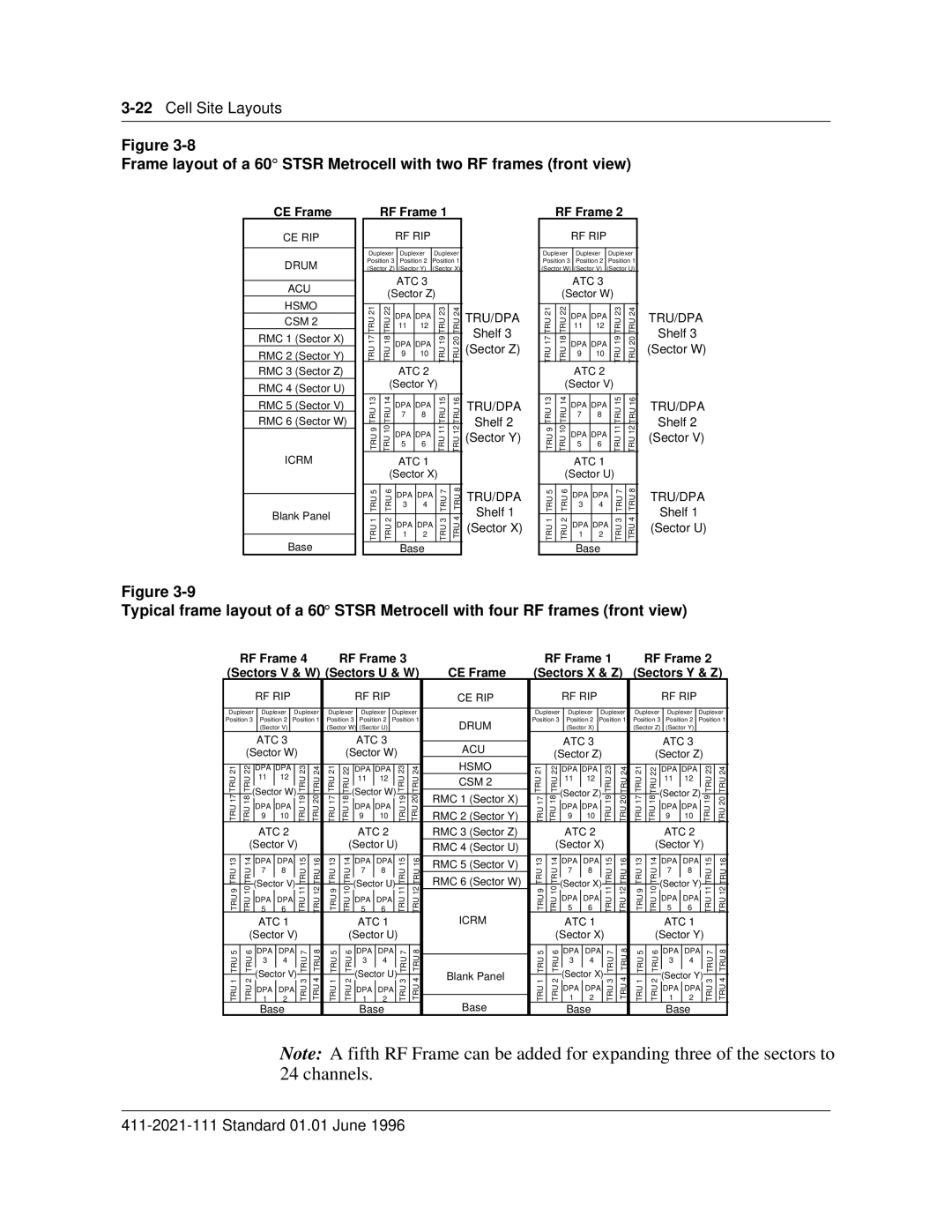
Figure
Frame layout of a 60° STSR Metrocell with two RF frames (front view)
CE Frame | RF Frame 1 |
RF Frame 2
CE RIP
DRUM
ACU
HSMO
CSM 2
RMC 1 (Sector X)
RMC 2 (Sector Y)
RMC 3 (Sector Z)
RMC 4 (Sector U)
RMC 5 (Sector V)
RMC 6 (Sector W)
ICRM
Blank Panel
Base
RF RIP
Duplexer | Duplexer | Duplexer |
Position 3 | Position 2 | Position 1 |
(Sector Z) | (Sector Y) | (Sector X) |
ATC 3
(Sector Z)
21 | 22 | DPA | DPA |
| 23 | 24 | ||
TRU17 | TRU18 |
| TRU19 | TRU20 | ||||
11 |
| 12 |
| |||||
|
|
|
|
|
| |||
|
|
|
|
|
|
| ||
TRU | TRU | DPA | DPA |
| TRU | TRU | ||
9 |
| 10 |
| |||||
|
|
|
|
|
| |||
|
|
|
|
|
|
|
| |
|
| ATC 2 |
|
| ||||
| (Sector Y) |
|
| |||||
|
|
|
|
|
|
|
| |
13 | 14 | DPA | DPA |
| 15 | 16 | ||
TRU | TRU |
| TRU | TRU | ||||
7 |
| 8 |
| |||||
|
|
|
|
|
| |||
|
|
|
|
|
|
|
| |
TRU9 | TRU10 | DPA | DPA |
| TRU11 | TRU12 | ||
|
| 5 |
| 6 |
|
|
| |
|
|
|
|
|
|
|
| |
|
| ATC 1 |
|
| ||||
| (Sector X) |
|
| |||||
|
|
|
|
|
|
|
| |
5 | 6 | DPA | DPA | 7 | 8 | |||
TRU | TRU | TRU | TRU | |||||
3 |
| 4 |
| |||||
|
|
|
|
|
|
|
| |
1 | 2 | DPA | DPA | 3 | 4 | |||
TRU | TRU | TRU | TRU | |||||
1 |
| 2 |
| |||||
|
|
|
|
|
| |||
|
|
|
|
|
|
|
| |
Base
TRU/DPA
Shelf 3
(Sector Z)
TRU/DPA
Shelf 2
(Sector Y)
TRU/DPA
Shelf 1
(Sector X)
RF RIP
Duplexer Duplexer Duplexer
Position 3 Position 2 Position 1
(Sector W) (Sector V) (Sector U)
ATC 3
(Sector W)
21 | 22 | DPA | DPA |
| 23 | 24 | ||
TRU17 | TRU18 |
| TRU19 | TRU20 | ||||
11 |
| 12 |
| |||||
|
|
|
|
|
| |||
|
|
|
|
|
|
| ||
TRU | TRU | DPA | DPA |
| TRU | TRU | ||
9 |
| 10 |
| |||||
|
|
|
|
|
| |||
|
|
|
|
|
|
|
| |
|
| ATC 2 |
|
| ||||
| (Sector V) |
|
| |||||
|
|
|
|
|
|
|
| |
13 | 14 | DPA | DPA |
| 15 | 16 | ||
TRU | TRU |
| TRU | TRU | ||||
7 |
| 8 |
| |||||
|
|
|
|
|
| |||
|
|
|
|
|
|
|
| |
TRU9 | TRU10 | DPA | DPA |
| TRU11 | TRU12 | ||
|
| 5 |
| 6 |
|
|
| |
|
|
|
|
|
|
|
| |
|
| ATC 1 |
|
| ||||
| (Sector U) |
|
| |||||
|
|
|
|
|
|
|
| |
5 | 6 | DPA | DPA | 7 | 8 | |||
TRU | TRU | TRU | TRU | |||||
3 |
| 4 |
| |||||
|
|
|
|
|
|
|
| |
1 | 2 | DPA | DPA | 3 | 4 | |||
TRU | TRU | TRU | TRU | |||||
1 |
| 2 |
| |||||
|
|
|
|
|
| |||
|
|
|
|
|
|
|
| |
Base
TRU/DPA
Shelf 3
(Sector W)
TRU/DPA
Shelf 2
(Sector V)
TRU/DPA
Shelf 1
(Sector U)
Figure
Typical frame layout of a 60° STSR Metrocell with four RF frames (front view)
| RF Frame 4 |
|
| RF Frame 3 |
|
|
| RF Frame 1 |
|
| RF Frame 2 |
| ||||||||||||||||||||||||||||
(Sectors V & W) (Sectors U & W) | CE Frame | (Sectors X & Z) | (Sectors Y & Z) | |||||||||||||||||||||||||||||||||||||
|
| RF RIP |
|
|
|
|
|
| RF RIP |
|
|
|
| CE RIP |
|
| RF RIP |
|
|
|
|
|
| RF RIP |
|
|
|
| ||||||||||||
|
|
|
|
|
|
|
|
|
|
|
|
|
|
|
|
|
|
|
|
|
|
|
|
|
|
|
|
|
|
|
|
|
|
|
| |||||
Duplexer | Duplexer |
|
| Duplexer | Duplexer |
| Duplexer |
| Duplexer |
| Duplexer | Duplexer |
| Duplexer | Duplexer | Duplexer |
| Duplexer | ||||||||||||||||||||||
Position 3 | Position 2 |
| Position 1 | Position 3 |
| Position 2 |
| Position 1 | DRUM | Position 3 | Position 2 | Position 1 | Position 3 | Position 2 |
| Position 1 | ||||||||||||||||||||||||
|
| (Sector V) |
|
|
|
|
| (Sector W) | (Sector U) |
|
|
|
|
|
|
| (Sector X) |
|
|
|
| (Sector Z) | (Sector Y) |
|
|
|
|
| ||||||||||||
|
| ATC 3 |
|
|
|
|
|
|
| ATC 3 |
|
|
|
|
|
|
| ATC 3 |
|
|
|
|
|
| ATC 3 |
|
|
|
| |||||||||||
|
|
|
|
|
|
|
|
|
|
|
| ACU |
|
|
|
|
|
|
|
|
|
|
|
| ||||||||||||||||
| (Sector W) |
|
|
| (Sector W) |
|
|
| (Sector Z) |
|
|
| (Sector Z) |
|
| |||||||||||||||||||||||||
|
|
|
|
|
| HSMO |
|
|
|
|
|
| ||||||||||||||||||||||||||||
|
|
|
|
|
|
|
|
|
|
|
|
|
|
|
|
|
|
|
|
|
|
|
|
|
|
|
|
|
|
|
|
|
|
|
| |||||
21 | 22 | DPA | DPA |
|
| 23 | 24 | 21 | 22 | DPA | DPA |
|
| 23 | 24 | 21 | 22 | DPA | DPA |
|
| 23 | 24 | 21 | 22 | DPA | DPA |
|
| 23 | 24 | |||||||||
TRU | TRU | 11 |
| 12 |
|
|
| TRU | TRU | TRU | TRU | 11 |
| 12 |
|
|
| TRU | TRU | CSM 2 | TRU | TRU | 11 |
| 12 |
|
| TRU | TRU | TRU | TRU | 11 |
| 12 |
|
|
| TRU | TRU | |
(Sector W) |
| (Sector W) |
| (Sector Z) |
| (Sector Z) |
| |||||||||||||||||||||||||||||||||
|
|
|
|
|
|
|
|
|
|
|
|
|
|
|
|
|
|
|
| |||||||||||||||||||||
TRU 17 | TRU18 |
| TRU19 | TRU20 | TRU17 | TRU18 |
| TRU19 | TRU20 | RMC 1 (Sector X) | TRU17 | TRU18 |
| TRU19 | TRU20 | TRU17 | TRU18 |
| TRU19 | TRU20 | ||||||||||||||||||||
DPA DPA |
|
| DPA DPA |
|
| DPA DPA |
|
| DPA DPA |
|
| |||||||||||||||||||||||||||||
|
|
|
| RMC 2 (Sector Y) |
|
|
|
| ||||||||||||||||||||||||||||||||
9 |
| 10 |
|
|
| 9 |
| 10 |
|
|
| 9 |
| 10 |
|
| 9 |
| 10 |
|
|
| ||||||||||||||||||
|
| ATC 2 |
|
|
|
|
|
|
| ATC 2 |
|
|
|
| RMC 3 (Sector Z) |
|
| ATC 2 |
|
|
|
|
|
| ATC 2 |
|
|
|
| |||||||||||
| (Sector V) |
|
|
| (Sector U) |
|
| RMC 4 (Sector U) |
| (Sector X) |
|
|
| (Sector Y) |
|
| ||||||||||||||||||||||||
|
|
|
|
|
|
|
|
|
|
|
|
|
|
|
|
|
|
|
|
|
|
|
|
|
|
|
|
|
|
|
|
|
|
|
|
|
|
|
| |
13 | 14 | DPA | DPA |
| 15 | 16 | 13 | 14 | DPA | DPA |
| 15 | 16 | RMC 5 (Sector V) | 13 | 14 | DPA | DPA |
| 15 | 16 | 13 | 14 | DPA | DPA |
| 15 | 16 | ||||||||||||
TRU | TRU | 7 |
| 8 |
|
|
| TRU | TRU | TRU | TRU | 7 |
| 8 |
|
|
| TRU | TRU |
| TRU | TRU | 7 |
| 8 |
|
| TRU | TRU | TRU | TRU | 7 |
| 8 |
|
|
| TRU | TRU | |
|
|
|
| RMC 6 (Sector W) |
|
|
|
|
|
|
| |||||||||||||||||||||||||||||
|
|
|
|
|
|
|
|
|
|
|
|
|
|
|
|
|
|
|
|
|
|
|
| |||||||||||||||||
TRU9 | TRU10 | (Sector V) |
| TRU11 | TRU12 | TRU9 | TRU10 | (Sector U) |
| TRU11 | TRU12 | TRU9 | TRU10 | (Sector X) |
| TRU11 | TRU12 | TRU9 | TRU10 | (Sector Y) |
| TRU11 | TRU12 | |||||||||||||||||
5 |
| 6 |
|
|
| 5 |
| 6 |
|
|
|
| 5 |
| 6 |
|
| 5 |
| 6 |
|
|
| |||||||||||||||||
|
| DPA DPA |
|
|
|
|
| DPA DPA |
|
|
|
|
|
| DPA DPA |
|
|
|
|
| DPA DPA |
|
|
| ||||||||||||||||
|
|
|
|
|
|
|
|
|
|
|
|
|
|
|
|
|
|
|
|
| ICRM |
|
|
|
|
|
|
|
|
|
|
|
|
|
|
|
|
|
| |
|
| ATC 1 |
|
|
|
|
|
|
| ATC 1 |
|
|
|
|
|
| ATC 1 |
|
|
|
|
|
| ATC 1 |
|
|
|
| ||||||||||||
| (Sector V) |
|
|
| (Sector U) |
|
|
|
| (Sector X) |
|
|
| (Sector Y) |
|
| ||||||||||||||||||||||||
|
|
|
|
|
|
|
|
|
|
|
|
|
|
|
|
|
|
|
|
|
|
|
|
|
|
|
|
|
|
|
|
|
|
|
|
|
| |||
5 | 6 | DPA | DPA | 7 | 8 | 5 | 6 |
| DPA | DPA | 7 | 8 |
| 5 | 6 | DPA | DPA | 7 | 8 | 5 | 6 | DPA | DPA | 7 | 8 | |||||||||||||||
TRU | TRU | 3 |
| 4 |
|
|
| TRU | TRU | TRU | TRU | 3 |
| 4 |
|
|
| TRU | TRU |
| TRU | TRU | 3 |
| 4 |
|
| TRU | TRU | TRU | TRU | 3 |
| 4 |
|
|
| TRU | TRU | |
|
|
|
|
|
|
|
|
|
|
|
|
|
|
|
|
|
|
|
|
|
|
|
|
|
|
|
|
|
|
|
| |||||||||
1 | 2 | (Sector V) | 3 | 4 | 1 | 2 | (Sector U) | 3 | 4 | Blank Panel | 1 | 2 | (Sector X) | 3 | 4 | 1 | 2 | (Sector Y) | 3 | 4 | ||||||||||||||||||||
TRU | TRU | 1 |
| 2 |
|
|
| TRU | TRU | TRU | TRU | 1 |
| 2 |
|
|
| TRU | TRU |
| TRU | TRU | 1 |
| 2 |
|
| TRU | TRU | TRU | TRU | 1 |
| 2 |
|
|
| TRU | TRU | |
|
| DPA DPA |
|
|
|
|
| DPA DPA |
|
|
|
|
| DPA DPA |
|
|
|
| DPA DPA |
|
| |||||||||||||||||||
|
|
|
|
|
|
|
|
|
|
|
|
|
|
|
|
|
|
|
|
| Base |
|
|
|
|
|
|
|
|
|
|
|
|
|
|
|
|
|
|
|
|
| Base |
|
|
|
|
|
|
| Base |
|
|
|
|
|
| Base |
|
|
|
|
|
| Base |
|
|
|
| ||||||||||||
Note: A fifth RF Frame can be added for expanding three of the sectors to 24 channels.