Frequency Assignment Example
An example configuration is shown in Figure
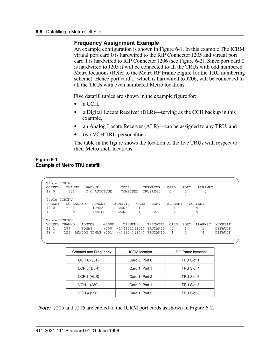
Five datafill tuples are shown in the example figure for:
•a CCH,
•a Digital Locate Receiver
•an Analog Locate Receiver
•two VCH TRU personalities.
The table in the figure shows the location of the five TRUs with respect to their Metro shelf locations.
Figure
Example of Metro TRU datafill
Table CCHINV |
|
|
|
|
|
|
|
|
|
|
|
| |||
CCHKEY |
| CHANNO | BACKUP |
|
| MODE |
| TERMATTR | CARD | PORT | ALRAMPT |
| |||
49 | 0 | 331 |
| Y 0 AUTOTUNE |
| COMBINED | TRU2AN60 | 0 | 0 | 0 |
| ||||
Table LCRINV |
|
|
|
|
|
|
|
|
|
|
|
| |||
LCRKEY |
| CCHBACKED | ADMODE | TERMATTR | CARD | PORT | ALARMPT | LCRTEST |
| ||||||
49 | 0 |
| Y 0 |
| TDMA3 |
| TRU2AN60 | 1 |
| 1 | 1 |
| N |
| |
49 | 1 |
| N |
| ANALOG | TRU2AN60 | 1 |
| 2 | 2 |
| N |
| ||
Table VCHINV |
|
|
|
|
|
|
|
|
|
|
|
| |||
VCHKEY CHANNO | ADMODE | GROUP | TRKMEMS |
| TERMATTR | CARD | PORT | ALARMPT | XCVRSAT | ||||||
49 | 1 | 289 | TDMA3 | (000) (1)(101)(201) TRU2AN60 | 0 | 1 | 1 | DEFAULT | |||||||
49 | 4 | 226 | ANALOG_TDMA3 (001) (4)(104)(204) TRU2AN60 | 1 | 3 | 4 | DEFAULT | ||||||||
|
|
|
|
|
|
|
| ||||||||
|
|
| Channel and Frequency |
| ICRM location | RF Frame location |
| ||||||||
|
|
|
|
|
|
|
|
|
| ||||||
|
|
|
| CCH 0 (331) |
|
| Card 0 Port 0 | TRU Slot 1 |
| ||||||
|
|
|
|
|
|
|
|
|
| ||||||
|
|
|
| LCR 0 (DLR) |
|
| Card 1 Port 1 | TRU Slot 4 |
| ||||||
|
|
|
|
|
|
|
|
|
| ||||||
|
|
|
| LCR 1 (ALR) |
|
| Card 1 Port 2 | TRU Slot 6 |
| ||||||
|
|
|
|
|
|
|
|
|
| ||||||
|
|
|
| VCH 1 (289) |
|
| Card 0 Port 1 | TRU Slot 3 |
| ||||||
|
|
|
|
|
|
|
|
|
| ||||||
|
|
|
| VCH 4 (226) |
|
| Card 1 Port 3 | TRU Slot 8 |
| ||||||
|
|
|
|
|
|
|
|
|
|
|
|
|
|
|
|
Note: J205 and J206 are cabled to the ICRM port cards as shown in Figure