Cell Site Layouts 3-25
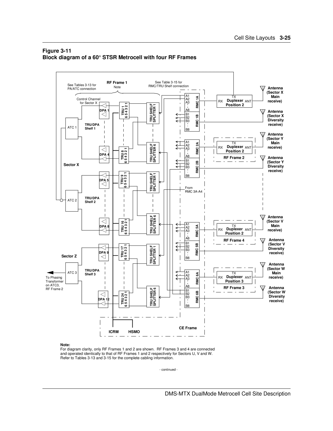
Figure
Block diagram of a 60° STSR Metrocell with four RF Frames
| RF Frame 1 | See Table |
|
|
|
| ||
See Tables | Note |
| RMC/TRU Shelf connection |
|
|
| ||
PA/ATC connection |
|
|
|
| ||||
|
|
|
|
|
| |||
|
|
|
|
|
|
| ||
|
|
|
|
| A1 | 1A |
| TX |
Control Channel |
|
|
| A2 | RX | Duplexer ANT | ||
| for Sector X |
| 34562 1 |
| A3 | 1BRMCRMC | ||
|
| SHELFTRU SPLITTER1 |
| Position 2 | ||||
| TRU/DPA | TRU1 |
|
| ||||
| A8 |
|
| |||||
| DPA 1 |
|
|
|
|
|
| |
|
|
|
|
| B1 |
|
|
|
|
|
|
|
| B2 |
|
|
|
|
|
|
|
| B3 |
|
|
|
ATC 1 | Shelf 1 |
|
|
| B8 |
|
|
|
|
|
|
|
|
|
| ||
|
|
|
|
|
|
|
| |
|
|
|
| SHELFTRU 6SPLITTER | A1 | 2ARMC2B |
| TX |
|
| 8TRU | 123456 | B2 |
| |||
|
|
|
|
| A2 |
| RX | Duplexer ANT |
|
|
|
|
| A3 |
| ||
|
|
|
|
|
|
| Position 2 | |
| DPA 4 |
|
|
|
|
|
| |
|
|
|
| A8 |
|
| RF Frame 2 | |
|
|
|
|
|
|
| ||
|
|
|
|
| B1 |
|
| |
Sector X |
|
|
|
|
|
|
| |
|
|
|
| B3 | RMC |
|
| |
|
| TRU9 | 34562 1 | SHELFTRU SPLITTER1 |
|
| ||
|
| B8 |
|
| ||||
|
|
|
|
|
|
|
| |
| DPA 5 |
|
|
|
|
|
|
|
|
|
|
|
| From |
|
|
|
|
|
|
|
| RMC |
|
| |
ATC 2 | TRU/DPA |
|
|
|
|
|
|
|
Shelf 2 |
|
|
|
|
|
|
| |
|
|
|
|
|
|
|
| |
|
|
|
|
|
|
|
|
|
|
|
|
|
|
|
|
|
|
|
|
|
|
|
|
|
|
|
|
|
|
|
|
|
|
|
|
|
|
|
|
|
|
|
|
|
|
|
|
|
|
|
|
|
|
|
|
|
|
|
|
|
|
|
|
|
|
|
|
|
|
|
|
|
|
|
|
|
|
|
|
|
|
|
|
|
|
|
|
|
|
|
|
|
|
|
|
|
|
| 16TRU | 23456 1 |
|
|
|
| SHELFTRU SPLITTER6 |
|
|
|
|
|
|
|
|
|
|
|
|
|
|
|
|
|
|
|
|
|
|
|
|
|
|
| ||
|
|
|
|
|
|
|
|
|
|
|
|
|
|
|
|
| A1 | 5ARMC |
|
|
|
|
|
|
|
|
|
|
|
|
|
|
|
|
|
|
|
|
| |||||
|
|
|
| DPA 8 |
|
|
|
|
|
|
|
|
|
|
|
|
|
| A2 |
|
|
|
|
|
|
|
|
|
| TX |
|
|
|
| ||||||||||
|
|
|
|
|
|
|
|
|
|
|
|
|
|
|
|
|
|
|
|
|
|
|
|
|
| RX |
| Duplexer ANT |
|
|
|
| ||||||||||||
|
|
|
|
|
|
|
|
|
|
|
|
|
|
|
|
|
|
|
|
|
| A3 |
|
|
|
|
|
|
|
|
| |||||||||||||
|
|
|
|
|
|
|
|
|
|
|
|
|
|
|
|
|
|
|
|
|
|
|
|
|
|
|
|
| ||||||||||||||||
|
|
|
|
|
|
|
|
|
|
|
|
|
|
|
|
|
|
|
|
|
|
|
|
|
|
|
| |||||||||||||||||
|
|
|
|
|
|
|
|
|
|
|
|
|
|
|
|
|
|
|
|
|
| A8 |
|
|
|
|
|
|
|
| Position 2 |
|
|
|
| |||||||||
|
|
|
|
|
|
|
|
|
|
|
|
|
|
|
|
|
|
|
|
|
|
|
|
|
|
|
|
| RF Frame 4 |
|
|
|
| |||||||||||
|
|
|
|
|
|
|
|
|
| 34562 1 |
|
|
|
|
|
|
|
|
|
|
| B1 | RMC5B |
|
|
|
|
|
|
|
|
|
|
|
|
|
|
|
|
|
|
|
|
|
|
|
|
|
|
|
|
|
| 17TRU |
|
|
|
| SHELFTRU SPLITTER1 |
|
|
|
| B2 |
|
|
|
|
|
|
|
|
|
|
|
|
|
|
|
|
|
|
|
|
| ||||
Sector Z |
| DPA 9 |
|
|
|
|
|
|
|
|
|
|
|
|
|
| B3 |
|
|
|
|
|
|
|
|
|
|
|
|
|
|
|
|
|
|
|
|
|
| |||||
|
|
|
|
|
|
|
|
|
|
|
|
|
|
| B8 |
|
|
|
|
|
|
|
|
|
|
|
|
|
|
|
|
|
|
|
|
|
| |||||||
|
|
|
|
|
|
|
|
|
|
|
|
|
|
|
|
|
|
|
|
|
|
|
|
|
|
|
|
|
|
|
|
|
|
|
|
|
|
|
|
| ||||
|
|
|
|
|
|
|
|
|
|
|
|
|
|
|
|
|
|
|
|
|
|
|
|
|
|
|
|
|
|
|
|
|
|
|
|
|
|
|
|
|
|
|
| |
|
|
|
|
|
|
|
|
|
|
|
|
|
|
|
|
|
|
|
|
|
|
|
|
|
|
|
|
|
|
|
|
|
|
|
|
|
|
|
|
|
|
|
|
|
Antenna (Sector X Main receive)
Antenna
(Sector X
Diversity
receive)
Antenna (Sector Y Main receive)
Antenna
(Sector Y
Diversity
receive)
Antenna (Sector V Main receive)
Antenna
(Sector V
Diversity
receive)
Antenna (Sector W
To Phasing Transformer on ATC3, RF Frame 2
ATC 3
TRU/DPA
Shelf 3
DPA 12
TRU 24 6 5 4 3 2 1
TRU SHELF SPLITTER 6
![]() A1
A1
![]()
![]() A2
A2
![]()
![]() A3
A3
A8
![]() B1 B2
B1 B2 ![]()
![]() B3
B3
B8
RMC 6B RMC 6A
TX
![]() RX Duplexer ANT
RX Duplexer ANT ![]()
Position 3
RF Frame 3
Main receive)
Antenna
(Sector W
Diversity
receive)
CE Frame
ICRM HSMO
Note:
For diagram clarity, only RF Frames 1 and 2 are shown. RF Frames 3 and 4 are connected and operated identically to that of RF Frames 1 and 2 respectively for Sectors U, V and W. Refer to Tables
- continued -