Checking the Voltage{ XE "Scanner installation:Check the voltage" }
Before you plug the 5000i scanner into the designated wall outlet, the following power and grounding requirements must be met and maintained to ensure optimum performance of the scanner and its peripherals. To verify that the power and grounding requirements have been met, refer to the following topics: Power Noise, Grounding, and Site Power Wiring{ XE "Wiring" \t "See Site power wiring recommendations" } Recommendations.
Power Noise
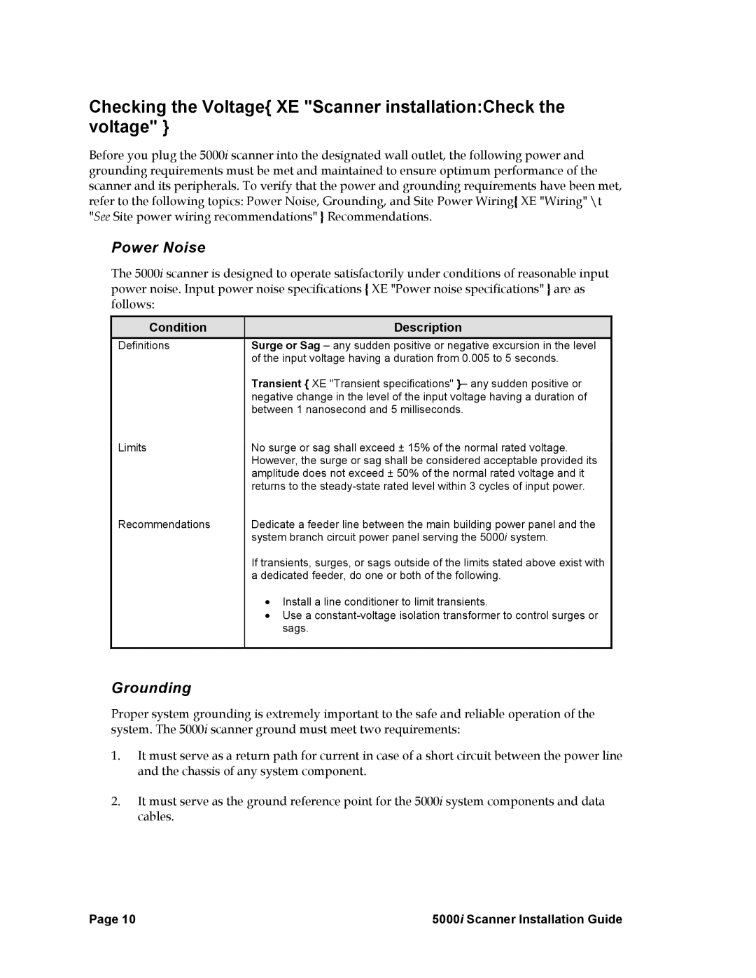
The 5000i scanner is designed to operate satisfactorily under conditions of reasonable input power noise. Input power noise specifications { XE "Power noise specifications" } are as follows:
Condition | Description |
Definitions | Surge or Sag – any sudden positive or negative excursion in the level |
| of the input voltage having a duration from 0.005 to 5 seconds. |
| Transient { XE "Transient specifications" }– any sudden positive or |
| negative change in the level of the input voltage having a duration of |
| between 1 nanosecond and 5 milliseconds. |
Limits | No surge or sag shall exceed ± 15% of the normal rated voltage. |
| However, the surge or sag shall be considered acceptable provided its |
| amplitude does not exceed ± 50% of the normal rated voltage and it |
| returns to the |
Recommendations | Dedicate a feeder line between the main building power panel and the |
| system branch circuit power panel serving the 5000i system. |
| If transients, surges, or sags outside of the limits stated above exist with |
| a dedicated feeder, do one or both of the following. |
| • Install a line conditioner to limit transients. |
| • Use a |
| sags. |
|
|
Grounding
Proper system grounding is extremely important to the safe and reliable operation of the system. The 5000i scanner ground must meet two requirements:
1.It must serve as a return path for current in case of a short circuit between the power line and the chassis of any system component.
2.It must serve as the ground reference point for the 5000i system components and data cables.
Page 10 | 5000i Scanner Installation Guide |
