Electrical Requirements{ XE "Scanner installation:Electrical requirements" }
The
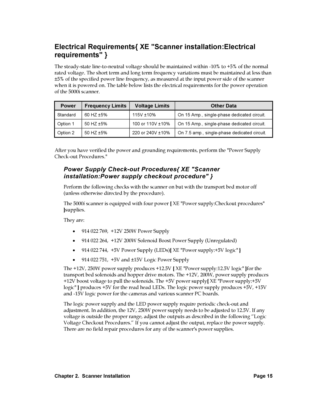
Power | Frequency Limits | Voltage Limits | Other Data |
Standard | 60 HZ ±5% | 115V ±10% | On 15 Amp., |
|
|
|
|
Option 1 | 50 HZ ±5% | 100 or 110V ±10% | On 15 Amp., |
|
|
|
|
Option 2 | 50 HZ ±5% | 220 or 240V ±10% | On 7.5 amp., |
|
|
|
|
After you have verified the power and grounding requirements, perform the "Power Supply
Power Supply
Perform the following checks with the scanner on but with the transport bed motor off (unless otherwise directed by the procedure).
The 5000i scanner is equipped with four power { XE "Power supply:Checkout procedures" }supplies.
They are:
•914 022 769, +12V 250W Power Supply
•914 022 264, +12V 200W Solenoid Boost Power Supply (Unregulated)
•914 022 744, +5V Power Supply (LEDs){ XE "Power supply:+5V logic" }
•914 022 751, +5V and ±15V Logic Power Supply
The +12V, 250W power supply produces +12.5V { XE "Power supply:12.5V logic" }for the transport bed solenoids and hopper drive motors. The +12V, 200W, power supply produces +12V boost voltage to pull the solenoids. The +5V power supply{ XE "Power supply:+5V logic" } produces +5V for the read head LEDs. The logic power supply produces +5V, +15V and
The logic power supply and the LED power supply require periodic
Chapter 2. Scanner Installation | Page 15 |