Board/Connector Relationship
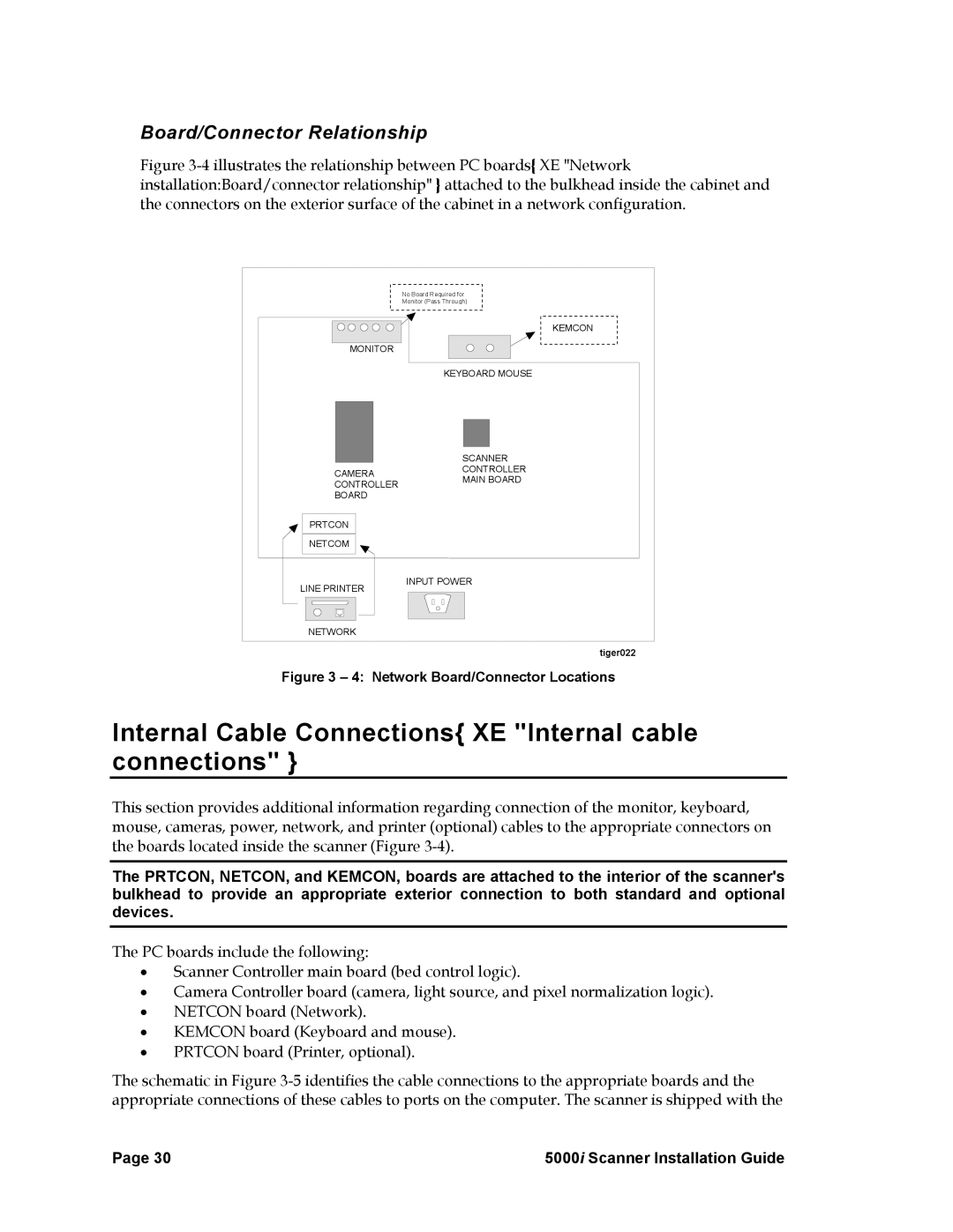
Figure 3-4 illustrates the relationship between PC boards{ XE "Network installation:Board/connector relationship" } attached to the bulkhead inside the cabinet and the connectors on the exterior surface of the cabinet in a network configuration.
| No Board Required for | |
| Monitor (Pass Through) | |
| KEMCON | |
MONITOR |
| |
| KEYBOARD MOUSE | |
| SCANNER | |
CAMERA | CONTROLLER | |
MAIN BOARD | ||
CONTROLLER | ||
| ||
BOARD |
| |
PRTCON |
| |
NETCOM |
| |
LINE PRINTER | INPUT POWER | |
| ||
NETWORK |
| |
| tiger022 | |
Figure 3 – 4: Network Board/Connector Locations | ||
Internal Cable Connections{ XE "Internal cable connections" }
This section provides additional information regarding connection of the monitor, keyboard, mouse, cameras, power, network, and printer (optional) cables to the appropriate connectors on the boards located inside the scanner (Figure
The PRTCON, NETCON, and KEMCON, boards are attached to the interior of the scanner's bulkhead to provide an appropriate exterior connection to both standard and optional devices.
The PC boards include the following:
•Scanner Controller main board (bed control logic).
•Camera Controller board (camera, light source, and pixel normalization logic).
•NETCON board (Network).
•KEMCON board (Keyboard and mouse).
•PRTCON board (Printer, optional).
The schematic in Figure
Page 30 | 5000i Scanner Installation Guide |