Board/Connector Relationship
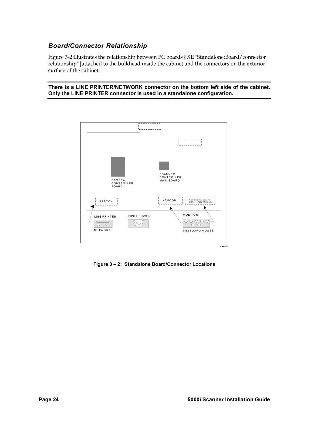
Figure 3-2 illustrates the relationship between PC boards { XE "Standalone:Board/connector relationship" }attached to the bulkhead inside the cabinet and the connectors on the exterior surface of the cabinet.
There is a LINE PRINTER/NETWORK connector on the bottom left side of the cabinet. Only the LINE PRINTER connector is used in a standalone configuration.
SCANNE R CONTRO LLER
CAMERAMAIN BO ARD CONTROLLER
BOARD
PRTCON |
| KEMCON |
|
| |
|
|
|
|
|
|
N o B oard R equired for M onitor (P ass Through)
LINE PRINTER | INPUT POW ER | MONITOR |
| ||
NETW ORK |
| KEYBO ARD MOU SE |
tiger021
Figure 3 – 2: Standalone Board/Connector Locations
Page 24 | 5000i Scanner Installation Guide |