Logic Voltage
The outputs of the power supplies { XE "Power supplies, multivolt logic:Adjustment" } { XE "Power supplies, multivolt logic:Voltage checkout procedure" }{ XE "Logic power supplies" \t "See power supplies, multivolt logic" }are read at their most critical
1.Turn on the scanner power switch.
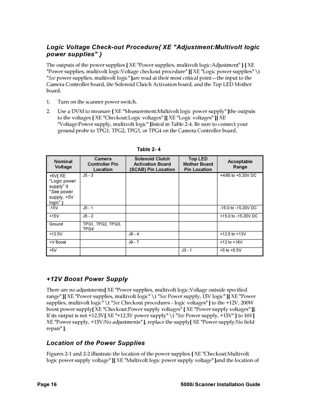
2.Use a DVM to measure { XE "Measurement:Multivolt logic power supply" }the outputs to the voltages { XE "Checkout:Logic voltages" }{ XE "Logic voltages" }{ XE "Voltage:Power supply, multivolt logic" }listed in Table
Table 2- 4
| Nominal |
| Camera | Solenoid Clutch | Top LED |
| Acceptable |
|
|
| Controller Pin | Activation Board | Mother Board |
|
| ||
| Voltage |
|
| Range |
| |||
|
| Location | (SCAB) Pin Location | Pin Location |
|
| ||
|
|
|
|
|
| |||
| +5V{ XE | J5 - 3 |
|
|
| +4/95 to +5.20V DC | ||
| "Logic power |
|
|
|
|
|
| |
| supply" \t |
|
|
|
|
|
| |
| "See power |
|
|
|
|
|
| |
| supply, +5V |
|
|
|
|
|
| |
| logic" } |
|
|
|
|
|
| |
| J5 - 1 |
|
| |||||
|
|
|
|
|
| |||
| +15V | J5 - 2 |
|
| +15.0 to | |||
|
|
|
|
|
|
|
| |
| Ground | TPG1, TPG2, TPG3, |
|
|
|
|
| |
|
|
| TPG4 |
|
|
|
|
|
| +12.5V |
| J9 - 4 |
| +12.5 to +13V | |||
|
|
|
|
|
| |||
| +V Boost |
| J9 - 7 |
| +12 to +16V | |||
|
|
|
|
|
| |||
| +5V |
|
| J3 - 1 | +5 to +5.5V | |||
|
|
|
|
|
|
|
|
|
+12V Boost Power Supply
There are no adjustments{ XE "Power supplies, multivolt logic:Voltage outside specified range" }{ XE "Power supplies, multivolt logic" \t "See Power supply, 15V logic" }{ XE "Power supplies, multivolt logic" \t "See Checkout procedures - logic voltages" } to the +12V, 200W boost power supply{ XE "Checkout:Power supply voltages" { XE "Power supply voltages" }}. If its output is not +12.5V{ XE "+12.5V power supply" \t "See Power supply, +15V" } to 16V{ XE "Power supply, +15V:No adjustments" }, replace the supply{ XE "Power supply:No field repair" }.
Location of the Power Supplies
Figures 2-1 and 2-2 illustrate the location of the power supplies { XE "Checkout:Multivolt logic power supply voltage" }{ XE "Multivolt logic power supply voltage" }and the location of
Page 16 | 5000i Scanner Installation Guide |