UM10310_1 © NXP B.V. 2008. All rights reserved.
User manual Rev. 01 — 1 December 2008 106 of 139
NXP Semiconductors UM10310
P89LPC9321 User manual
Figure 51 shows the Watchdog Timer in Timer Mode. In this mode, any changes to
WDCON are written to the shadow register after one watchdog clock cycle. A watchdog
underflow will set the WDTOF bit. If IEN0.6 is set, the watchdog underflow is enabled to
cause an interrupt. WDTOF is cleared by writing a logic 0 to this bit in software. When an
underflow occurs, the contents of WDL is reloaded into the down counter and the
watchdog timer immediately begins to count down again.
A feed is necessary to cause WDL to be loaded into the down counter before an
underflow occurs. Incorrect feeds are ignored in this mode.
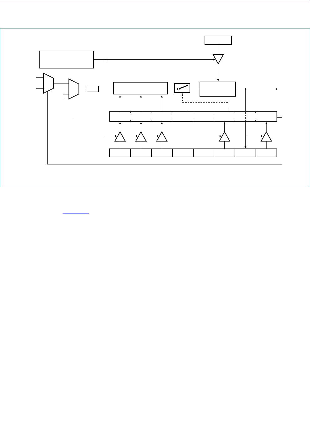
Fig 50. Watchdog Timer in Watchdog Mode (WDTE = 1).
PRE2 PRE1 PRE0 - - WDRUN WDTOF WDCLK
WDCON (A7H)
SHADOW REGISTER
PRESCALER
002aae093
8-BIT DOWN
COUNTER
WDL (C1H)
÷32
MOV WFEED1, #0A5H
MOV WFEED2, #05AH
reset
Watchdog
oscillator
external
crystal
oscillator
0
1
0
1
PCLK
XTALWD