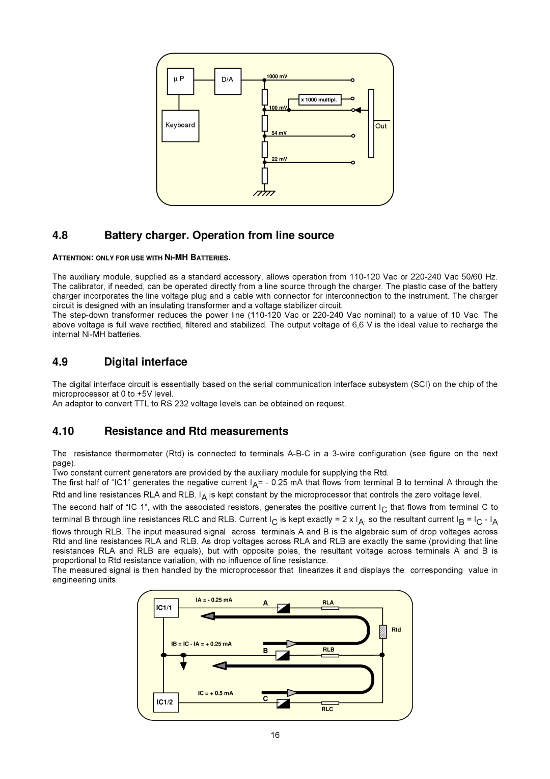
∝P
Keyboard
D/A
1000 mV
x 1000 multipl.
![]() 100 mV
100 mV
54 mV
22 mV
Out
4.8Battery charger. Operation from line source
ATTENTION: ONLY FOR USE WITH
The auxiliary module, supplied as a standard accessory, allows operation from
The
4.9Digital interface
The digital interface circuit is essentially based on the serial communication interface subsystem (SCI) on the chip of the microprocessor at 0 to +5V level.
An adaptor to convert TTL to RS 232 voltage levels can be obtained on request.
4.10Resistance and Rtd measurements
The resistance thermometer (Rtd) is connected to terminals
Two constant current generators are provided by the auxiliary module for supplying the Rtd.
The first half of “IC1” generates the negative current IA= - 0.25 mA that flows from terminal B to terminal A through the Rtd and line resistances RLA and RLB. IA is kept constant by the microprocessor that controls the zero voltage level. The second half of “IC 1”, with the associated resistors, generates the positive current IC that flows from terminal C to terminal B through line resistances RLC and RLB. Current IC is kept exactly = 2 x IA, so the resultant current IB = IC - IA flows through RLB. The input measured signal across terminals A and B is the algebraic sum of drop voltages across Rtd and line resistances RLA and RLB. As drop voltages across RLA and RLB are exactly the same (providing that line resistances RLA and RLB are equals), but with opposite poles, the resultant voltage across terminals A and B is proportional to Rtd resistance variation, with no influence of line resistance.
The measured signal is then handled by the microprocessor that linearizes it and displays the corresponding value in engineering units.
|
| IA = - 0.25 mA | A |
| |
IC1/1 |
| ||||
|
|
|
| ||
|
|
|
|
| |
|
|
|
|
|
|
|
|
|
|
|
|
IB = IC - IA = + 0.25 mA
B
|
|
|
|
|
|
|
|
|
| IC = + 0.5 mA | C |
|
| ||
IC1/2 |
| ||||||
|
|
|
|
|
| ||
|
|
|
|
|
|
| |
|
|
|
|
|
|
|
|
RLA
Rtd
RLB
RLC
16