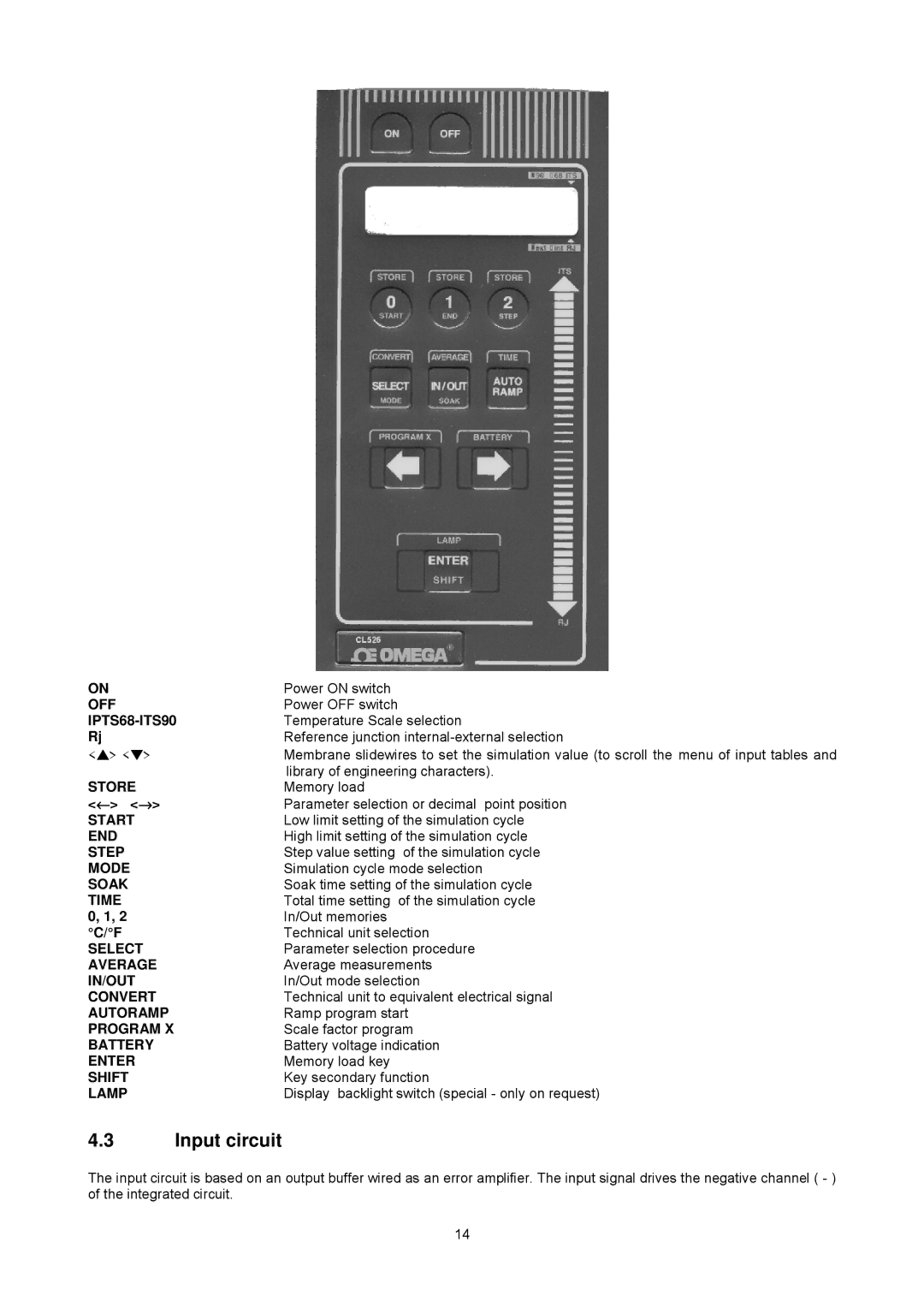
ON | Power ON switch |
OFF | Power OFF switch |
| Temperature Scale selection |
Rj | Reference junction |
<▲> <▼> | Membrane slidewires to set the simulation value (to scroll the menu of input tables and |
STORE | library of engineering characters). |
Memory load | |
<←> <→> | Parameter selection or decimal point position |
START | Low limit setting of the simulation cycle |
END | High limit setting of the simulation cycle |
STEP | Step value setting of the simulation cycle |
MODE | Simulation cycle mode selection |
SOAK | Soak time setting of the simulation cycle |
TIME | Total time setting of the simulation cycle |
0, 1, 2 | In/Out memories |
°C/°F | Technical unit selection |
SELECT | Parameter selection procedure |
AVERAGE | Average measurements |
IN/OUT | In/Out mode selection |
CONVERT | Technical unit to equivalent electrical signal |
AUTORAMP | Ramp program start |
PROGRAM X | Scale factor program |
BATTERY | Battery voltage indication |
ENTER | Memory load key |
SHIFT | Key secondary function |
LAMP | Display backlight switch (special - only on request) |
4.3Input circuit
The input circuit is based on an output buffer wired as an error amplifier. The input signal drives the negative channel ( - ) of the integrated circuit.
14