4 FUNCTIONAL DESCRIPTION
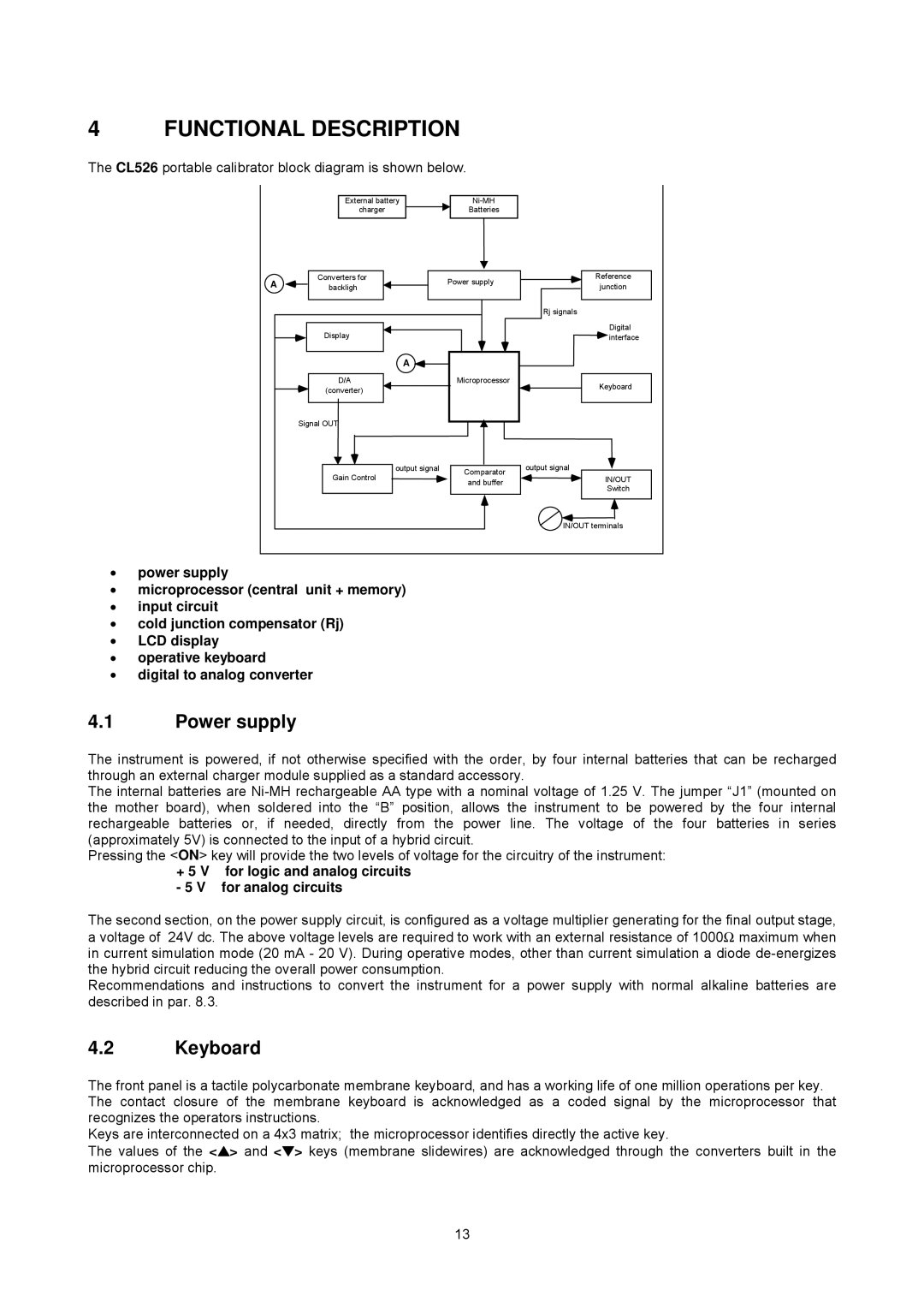
The CL526 portable calibrator block diagram is shown below.
| External battery |
| ||
| charger | Batteries |
| |
A | Converters for | Power supply | Reference | |
backligh | junction | |||
| ||||
|
|
| Rj signals | |
| Display |
| Digital | |
|
| interface | ||
| A |
|
| |
| D/A | Microprocessor | Keyboard | |
| (converter) |
| ||
|
|
| ||
| Signal OUT |
|
| |
| output signal | Comparator | output signal | |
| Gain Control | IN/OUT | ||
| and buffer | |||
|
| Switch | ||
|
|
| ||
|
|
| IN/OUT terminals |
•power supply
•microprocessor (central unit + memory)
•input circuit
•cold junction compensator (Rj)
•LCD display
•operative keyboard
•digital to analog converter
4.1Power supply
The instrument is powered, if not otherwise specified with the order, by four internal batteries that can be recharged through an external charger module supplied as a standard accessory.
The internal batteries are
Pressing the <ON> key will provide the two levels of voltage for the circuitry of the instrument:
+5 V for logic and analog circuits - 5 V for analog circuits
The second section, on the power supply circuit, is configured as a voltage multiplier generating for the final output stage, a voltage of 24V dc. The above voltage levels are required to work with an external resistance of 1000Ω maximum when in current simulation mode (20 mA - 20 V). During operative modes, other than current simulation a diode
Recommendations and instructions to convert the instrument for a power supply with normal alkaline batteries are described in par. 8.3.
4.2Keyboard
The front panel is a tactile polycarbonate membrane keyboard, and has a working life of one million operations per key. The contact closure of the membrane keyboard is acknowledged as a coded signal by the microprocessor that recognizes the operators instructions.
Keys are interconnected on a 4x3 matrix; the microprocessor identifies directly the active key.
The values of the <▲> and <▼> keys (membrane slidewires) are acknowledged through the converters built in the microprocessor chip.
13