7 ELECTRICAL CONNECTIONS
Appropriate extension wires should be used between the thermocouple (or instrument under calibration) and the CL526 unless the thermocouple leads permit direct connection.
Make sure that both thermocouple and compensating cable are connected with the correct polarity.
If in doubt, the polarity of the compensating leads can be checked by connecting a length of lead to the indicator, shorting the free ends of the wires together and noting that the indicator reading increases when the wires connection is heated.
Color codes of compensating cables change in different countries. Check the appropriate table. For Rtd connection use a cable of adequate gauge to lower the overall input resistance.
The use of a cable with a good resistance balance between conductors is also necessary.
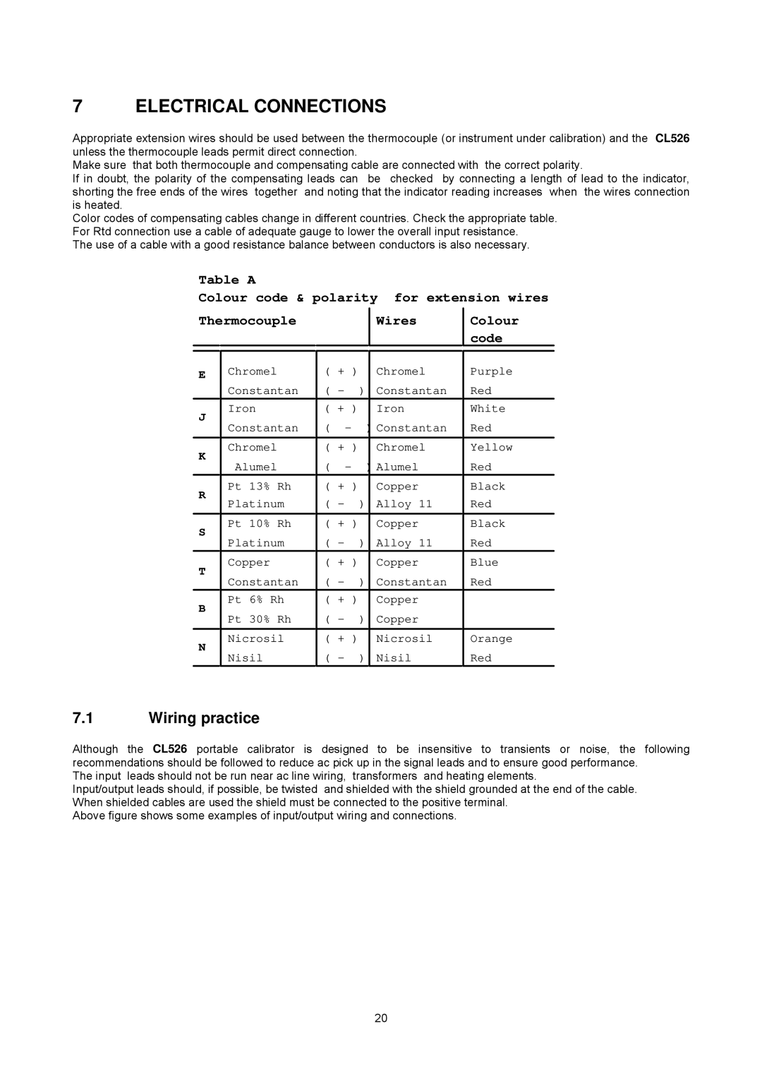
Table A
Colour code & polarity for extension wires
Thermocouple
EChromel Constantan
Iron
J
Constantan
Chromel
K
Alumel
Pt 13% Rh
R
Platinum
Pt 10% Rh
S
Platinum
Copper
T
Constantan
Pt 6% Rh
B
Pt 30% Rh
Nicrosil
N
Nisil
|
|
|
| Wires |
|
|
|
| |
|
|
|
| |
( + ) |
|
| Chromel | |
( - |
| ) |
| Constantan |
( + ) |
|
| Iron | |
( | - |
| ) Constantan | |
|
|
|
| |
( + ) |
|
| Chromel | |
( | - |
| ) Alumel | |
( + ) |
|
| Copper | |
( - |
| ) |
| Alloy 11 |
|
|
|
| |
( + ) |
|
| Copper | |
( - |
| ) |
| Alloy 11 |
( + ) |
|
| Copper | |
( - |
| ) |
| Constantan |
( + ) |
|
| Copper | |
( - |
| ) |
| Copper |
|
|
|
| |
( + ) |
|
| Nicrosil | |
( - |
| ) |
| Nisil |
Colour code
Purple Red
White
Red
Yellow Red
Black
Red
Black
Red
Blue
Red
Orange Red
7.1Wiring practice
Although the CL526 portable calibrator is designed to be insensitive to transients or noise, the following recommendations should be followed to reduce ac pick up in the signal leads and to ensure good performance.
The input leads should not be run near ac line wiring, transformers and heating elements.
Input/output leads should, if possible, be twisted and shielded with the shield grounded at the end of the cable. When shielded cables are used the shield must be connected to the positive terminal.
Above figure shows some examples of input/output wiring and connections.
20