4.11Resistance and Rtd simulation
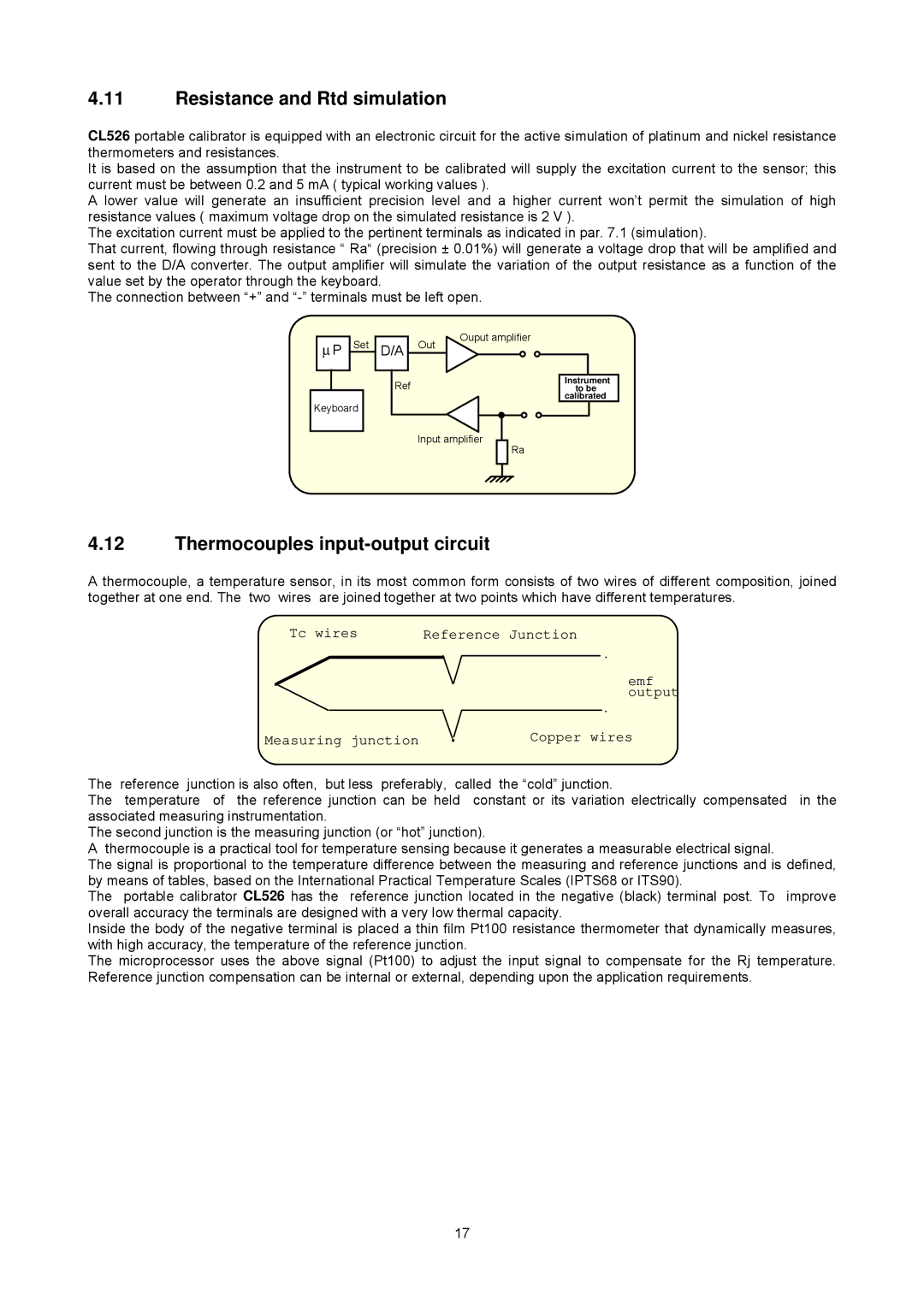
CL526 portable calibrator is equipped with an electronic circuit for the active simulation of platinum and nickel resistance thermometers and resistances.
It is based on the assumption that the instrument to be calibrated will supply the excitation current to the sensor; this current must be between 0.2 and 5 mA ( typical working values ).
A lower value will generate an insufficient precision level and a higher current won’t permit the simulation of high resistance values ( maximum voltage drop on the simulated resistance is 2 V ).
The excitation current must be applied to the pertinent terminals as indicated in par. 7.1 (simulation).
That current, flowing through resistance “ Ra“ (precision ± 0.01%) will generate a voltage drop that will be amplified and sent to the D/A converter. The output amplifier will simulate the variation of the output resistance as a function of the value set by the operator through the keyboard.
The connection between “+” and
∝ P Set
Keyboard |
D/A Out
Ref
Ouput amplifier
Instrument to be calibrated
Input amplifier
Ra
4.12Thermocouples input-output circuit
A thermocouple, a temperature sensor, in its most common form consists of two wires of different composition, joined together at one end. The two wires are joined together at two points which have different temperatures.
Tc wires | Reference Junction | ||
|
|
|
|
emf output
| Measuring junction | Copper wires |
The | reference junction is also often, but less preferably, called | the “cold” junction. |
The | temperature of the reference junction can be held constant or its variation electrically compensated in the | |
associated measuring instrumentation. |
| |
The second junction is the measuring junction (or “hot” junction). |
| |
A thermocouple is a practical tool for temperature sensing because it generates a measurable electrical signal.
The signal is proportional to the temperature difference between the measuring and reference junctions and is defined, by means of tables, based on the International Practical Temperature Scales (IPTS68 or ITS90).
The portable calibrator CL526 has the reference junction located in the negative (black) terminal post. To improve overall accuracy the terminals are designed with a very low thermal capacity.
Inside the body of the negative terminal is placed a thin film Pt100 resistance thermometer that dynamically measures, with high accuracy, the temperature of the reference junction.
The microprocessor uses the above signal (Pt100) to adjust the input signal to compensate for the Rj temperature. Reference junction compensation can be internal or external, depending upon the application requirements.
17