4 FUNCTIONAL DESCRIPTION
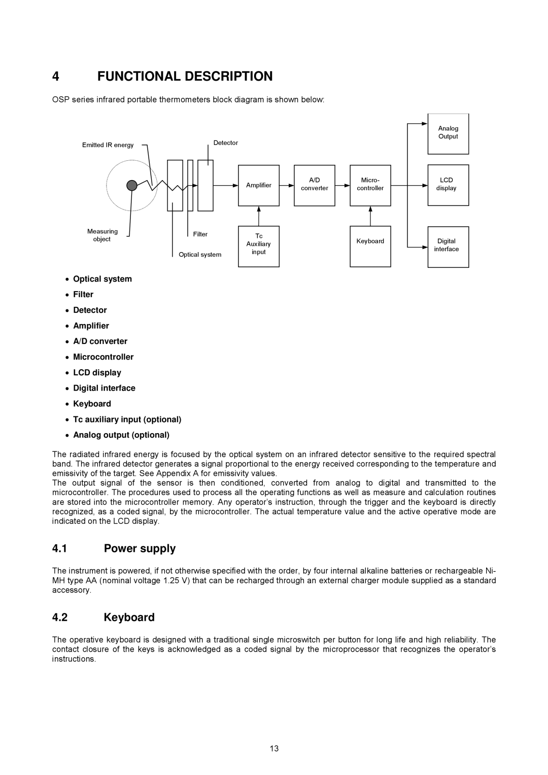
OSP series infrared portable thermometers block diagram is shown below:
Analog
Output
Emitted IR energy
Measuring object
Detector
Amplifier
Filter | Tc |
| Auxiliary |
Optical system | input |
| |
|
|
A/D
converter
Micro-
controller
Keyboard
LCD
display
Digital
interface
•Optical system
•Filter
•Detector
•Amplifier
•A/D converter
•Microcontroller
•LCD display
•Digital interface
•Keyboard
•Tc auxiliary input (optional)
•Analog output (optional)
The radiated infrared energy is focused by the optical system on an infrared detector sensitive to the required spectral band. The infrared detector generates a signal proportional to the energy received corresponding to the temperature and emissivity of the target. See Appendix A for emissivity values.
The output signal of the sensor is then conditioned, converted from analog to digital and transmitted to the microcontroller. The procedures used to process all the operating functions as well as measure and calculation routines are stored into the microcontroller memory. Any operator’s instruction, through the trigger and the keyboard is directly recognized, as a coded signal, by the microcontroller. The actual temperature value and the active operative mode are indicated on the LCD display.
4.1Power supply
The instrument is powered, if not otherwise specified with the order, by four internal alkaline batteries or rechargeable Ni- MH type AA (nominal voltage 1.25 V) that can be recharged through an external charger module supplied as a standard accessory.
4.2Keyboard
The operative keyboard is designed with a traditional single microswitch per button for long life and high reliability. The contact closure of the keys is acknowledged as a coded signal by the microprocessor that recognizes the operator’s instructions.
13