Index to parts and controls
Rear panel
1 | 2 | 3 | 4 | 5 |
|
|
|
|
|
| |
ANTENNA |
|
|
| FM | ||
AM | ||||||
75 | ||||||
|
| |||||
|
|
|
|
|
| |
|
|
|
|
|
| |
|
|
|
|
|
| |
FRONT |
| FRONT | ||
SPEAKERS A |
| SPEAKERS B | ||
|
|
|
|
|
L
SURROUND
SPEAKERS
L
CENTER
SPEAKER
AC OUTLET
DIGITAL INPUT
OPTICAL | COAXIAL | REMOTE | |
2 | 1 |
| CONTROL |
IN | OUT | IN |
|
SUBWOOFER |
|
| L |
|
|
| |
PRE OUT |
|
|
|
|
|
| R |
CD | TAPE |
| |
VIDEO 2 | VIDEO 1 | DVD MONITOR | |||
|
|
|
|
| OUT |
IN | OUT | IN |
| IN | |
VIDEO
S VIDEO
IN | OUT | IN | FRONT SURR CENTER |
|
|
| L |
|
|
| R |
VIDEO 2 | VIDEO 1 | SUB | |
WOOFER | |||
|
|
| DVD |
L
RR
R
VOLTAGE SELECTOR
120V ![]()
![]()
678 9 p q w
For operational instructions, refer to the page indicated in brackets. | 8 CD IN [10] |
e
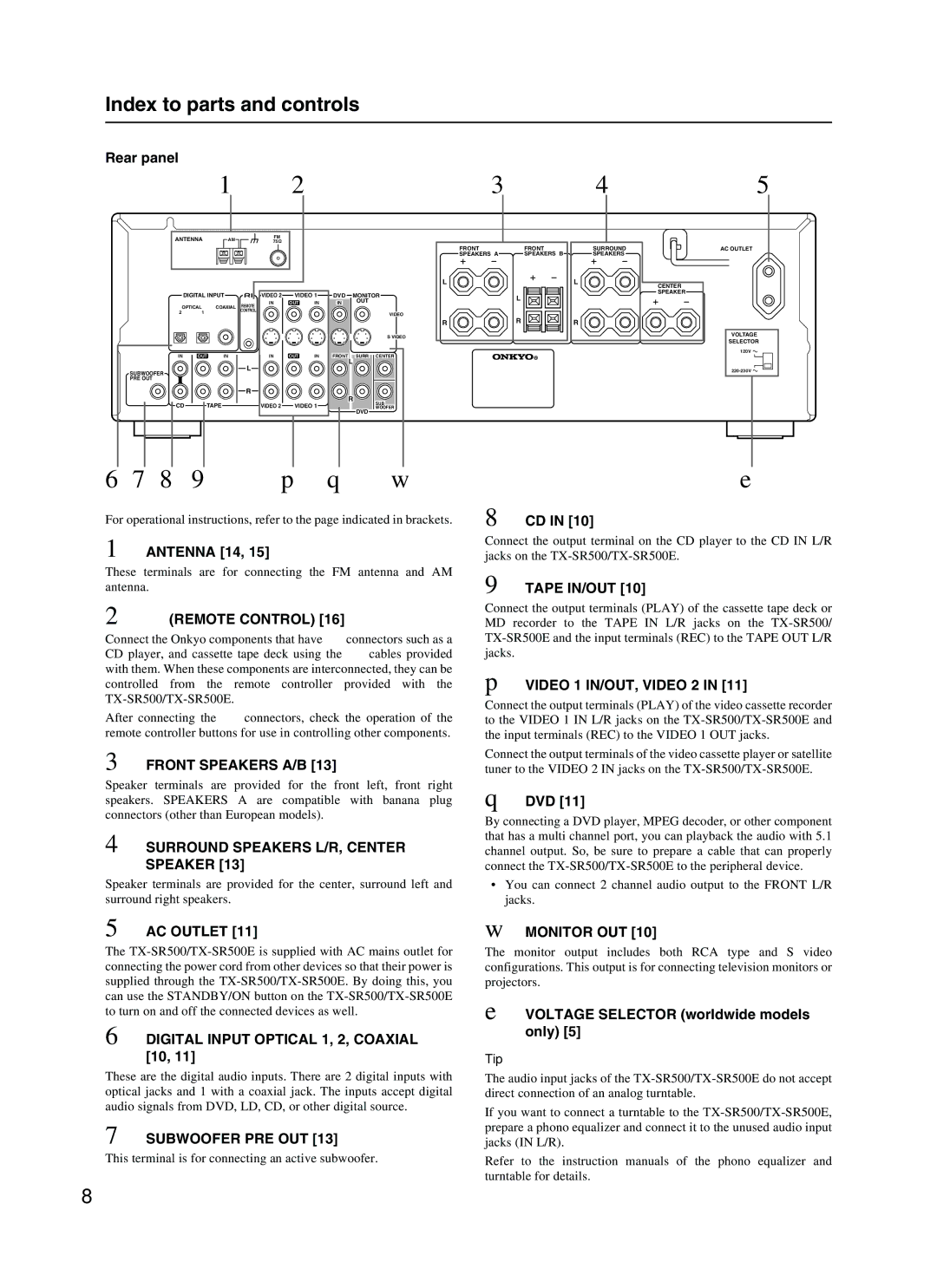
1ANTENNA [14, 15]
These terminals are for connecting the FM antenna and AM antenna.
2z(REMOTE CONTROL) [16]
Connect the Onkyo components that have zconnectors such as a CD player, and cassette tape deck using the z cables provided with them. When these components are interconnected, they can be controlled from the remote controller provided with the
After connecting the z connectors, check the operation of the remote controller buttons for use in controlling other components.
3FRONT SPEAKERS A/B [13]
Speaker terminals are provided for the front left, front right speakers. SPEAKERS A are compatible with banana plug connectors (other than European models).
4SURROUND SPEAKERS L/R, CENTER SPEAKER [13]
Speaker terminals are provided for the center, surround left and surround right speakers.
Connect the output terminal on the CD player to the CD IN L/R jacks on the
9TAPE IN/OUT [10]
Connect the output terminals (PLAY) of the cassette tape deck or MD recorder to the TAPE IN L/R jacks on the
pVIDEO 1 IN/OUT, VIDEO 2 IN [11]
Connect the output terminals (PLAY) of the video cassette recorder to the VIDEO 1 IN L/R jacks on the
Connect the output terminals of the video cassette player or satellite tuner to the VIDEO 2 IN jacks on the
qDVD [11]
By connecting a DVD player, MPEG decoder, or other component that has a multi channel port, you can playback the audio with 5.1 channel output. So, be sure to prepare a cable that can properly connect the
•You can connect 2 channel audio output to the FRONT L/R jacks.
5AC OUTLET [11]
The
6DIGITAL INPUT OPTICAL 1, 2, COAXIAL [10, 11]
These are the digital audio inputs. There are 2 digital inputs with optical jacks and 1 with a coaxial jack. The inputs accept digital audio signals from DVD, LD, CD, or other digital source.
7SUBWOOFER PRE OUT [13]
This terminal is for connecting an active subwoofer.
wMONITOR OUT [10]
The monitor output includes both RCA type and S video configurations. This output is for connecting television monitors or projectors.
eVOLTAGE SELECTOR (worldwide models only) [5]
Tip
The audio input jacks of the
If you want to connect a turntable to the
Refer to the instruction manuals of the phono equalizer and turntable for details.
8