2. | Position the Jupiter transmitter on the side of the MLI | |
| where it will be attached. Mark the location and the exact | |
| area where the clamps will be attached to hold the Jupiter | |
| in place. | |
3. | Attach the lower clamp and tighten so that it remains in | |
| place, but loose enough so that there is still room to place | |
| the guide tab from the Jupiter between the inside of the | |
| clamp and the outer diameter of the MLI chamber. See | |
| Figure 1. | |
4. | The upper clamp will need to be open to a large enough | |
Upper Clamp | diameter to be able to mount to the MLI as well as the | |
probe. The upper clamp should be positioned just above | ||
| ||
| the 3⁄4" NPT threads. See Figure 2. | |
5. | Mount the Jupiter guide pin in the lower clamp and tight- | |
| en. If necessary, use strapping tape to temporarily hold in | |
| place on the MLI. See Figure 1. | |
6. | Position the upper clamp to attach the unit to the MLI | |
| and tighten. See Figure 1. | |
7. | Discard any tape temporarily holding the Jupiter to the | |
Figure 2 | MLI. | |
| ||
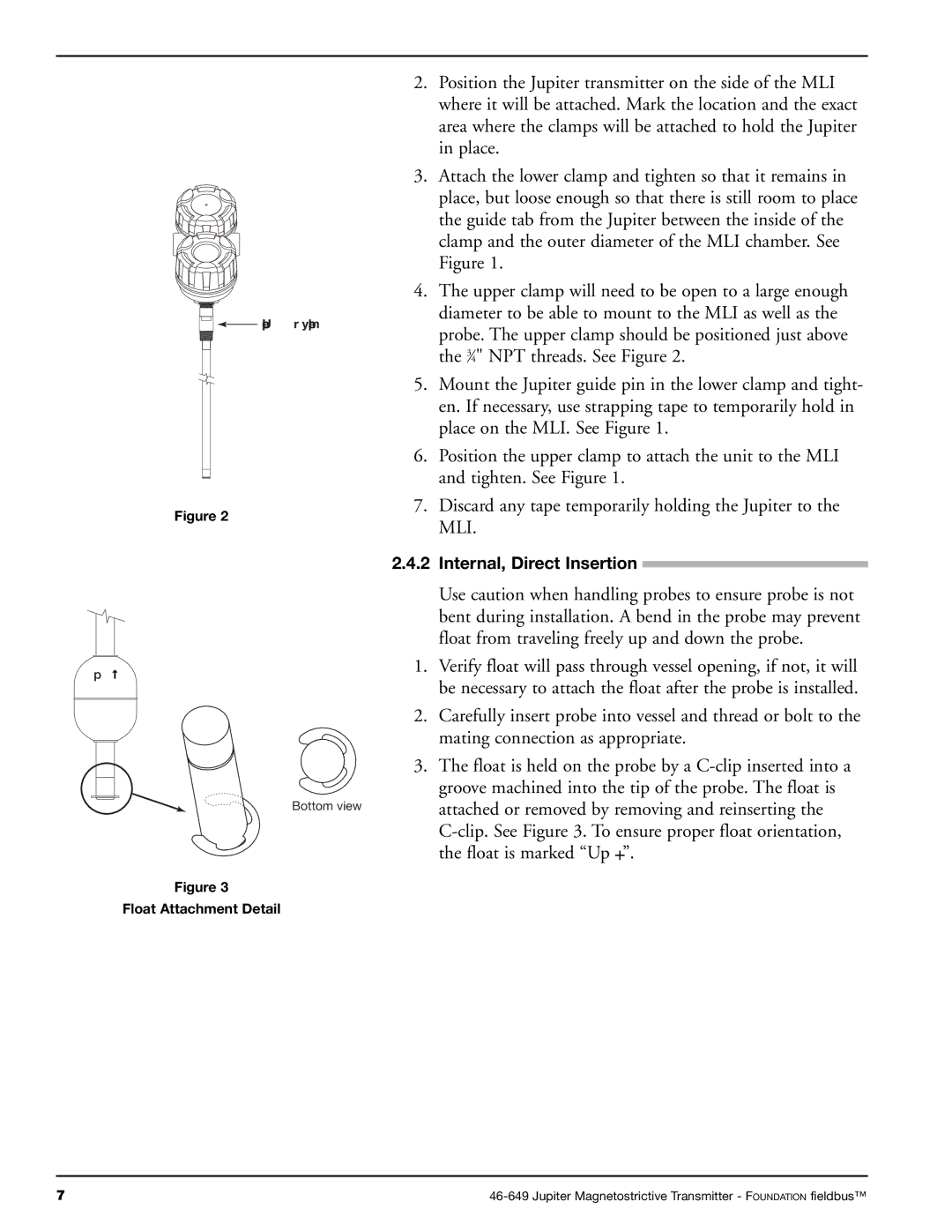
2.4.2 | Internal, Direct Insertion |
Up![]()
Bottom view
Figure 3
Float Attachment Detail
Use caution when handling probes to ensure probe is not bent during installation. A bend in the probe may prevent float from traveling freely up and down the probe.
1.Verify float will pass through vessel opening, if not, it will be necessary to attach the float after the probe is installed.
2.Carefully insert probe into vessel and thread or bolt to the mating connection as appropriate.
3.The float is held on the probe by a
7 |