Parts and their functions
U
V
Y W Z X
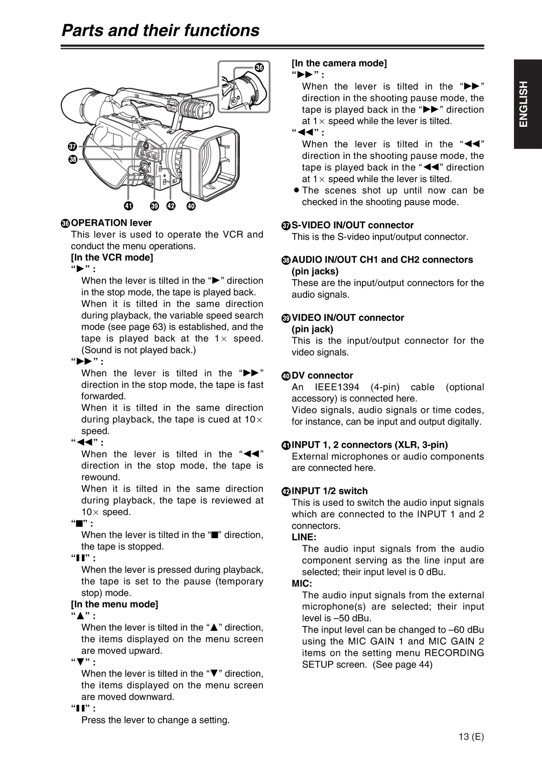
TOPERATION lever
T[In the camera mode] “5” :
When the lever is tilted in the “5” direction in the shooting pause mode, the tape is played back in the “5” direction at 1a speed while the lever is tilted.
“6” :
When the lever is tilted in the “6” direction in the shooting pause mode, the tape is played back in the “6” direction at 1a speed while the lever is tilted.
OThe scenes shot up until now can be checked in the shooting pause mode.
U
ENGLISH
This lever is used to operate the VCR and | This is the |
conduct the menu operations. |
|
[In the VCR mode] “1” :
When the lever is tilted in the “1” direction in the stop mode, the tape is played back. When it is tilted in the same direction during playback, the variable speed search mode (see page 63) is established, and the tape is played back at the 1a speed. (Sound is not played back.)
“5” :
VAUDIO IN/OUT CH1 and CH2 connectors (pin jacks)
These are the input/output connectors for the audio signals.
WVIDEO IN/OUT connector (pin jack)
This is the input/output connector for the video signals.
When the lever is tilted in the “5” | XDV connector |
direction in the stop mode, the tape is fast | An IEEE1394 |
forwarded. | accessory) is connected here. |
When it is tilted in the same direction | Video signals, audio signals or time codes, |
during playback, the tape is cued at 10a | for instance, can be input and output digitally. |
speed. |
|
“6” :
When the lever is tilted in the “6” direction in the stop mode, the tape is rewound.
When it is tilted in the same direction during playback, the tape is reviewed at 10a speed.
“$” :
When the lever is tilted in the “$” direction, the tape is stopped.
“;” :
When the lever is pressed during playback, the tape is set to the pause (temporary stop) mode.
[In the menu mode] “3” :
When the lever is tilted in the “3” direction, the items displayed on the menu screen are moved upward.
“4” :
When the lever is tilted in the “4” direction, the items displayed on the menu screen are moved downward.
“;” :
Press the lever to change a setting.
YINPUT 1, 2 connectors (XLR,
ZINPUT 1/2 switch
This is used to switch the audio input signals which are connected to the INPUT 1 and 2 connectors.
LINE:
The audio input signals from the audio component serving as the line input are selected; their input level is 0 dBu.
MIC:
The audio input signals from the external microphone(s) are selected; their input level is
The input level can be changed to
13 (E)