Connecting external components
Inputting to and outputting from analog components
$ When an external component is to be connected and its video and audio signals are to be input to the camera recorder, connect the camera recorder to the output connectors on the external component.
$ Conversely, when an external component is to be connected and the video and audio signals of the camera recorder are to be input to the component, connect the camera recorder to the input connectors on the external component.
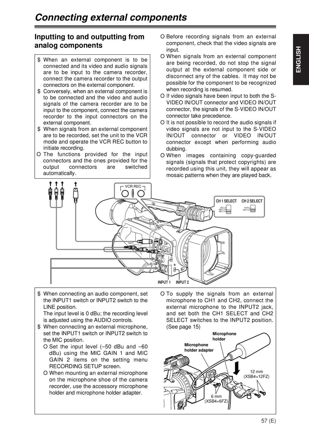
$ When signals from an external component are to be recorded, set the unit to the VCR mode and operate the VCR REC button to initiate recording.
O The functions provided for the input connectors and the ones provided for the
output connectors are switched automatically.
![]() VCR REC
VCR REC ![]()
OBefore recording signals from an external component, check that the video signals are input.
OWhen signals from an external component are being recorded, do not stop the signal output at the external component side or disconnect any of the cables. It may not be possible for the component to be recognized when recording is resumed.
O If video signals have been input to both the S- VIDEO IN/OUT connector and VIDEO IN/OUT connector, the signals of the
O It is not possible to record the audio signals if video signals are not input to the
OWhen images containing
CH 1 SELECT | CH 2 SELECT | ||||
INT(L) | INT(R) | ||||
INPUT 1 | INPUT 2 |
|
| ||
| |||||
INPUT 2 |
|
|
|
|
|
ENGLISH
INPUT 1 INPUT 2
$ When connecting an audio component, set the INPUT1 switch or INPUT2 switch to the LINE position.
The input level is 0 dBu; the recording level is adjusted using the AUDIO controls.
$ When connecting an external microphone, set the INPUT1 switch or INPUT2 switch to the MIC position.
OSet the input level
OWhen mounting an external microphone on the microphone shoe of the camera recorder, use the accessory microphone holder and microphone holder adapter.
OTo supply the signals from an external microphone to CH1 and CH2, connect the external microphone to the INPUT2 jack, and set both the CH1 SELECT and CH2 SELECT switches to the INPUT2 position. (See page 15)
Microphone holder
Microphone holder adapter
12 mm
(XSB4+12FZ)
6 mm
(XSB4+6FZ)
57 (E)