Screen displays
Camera mode and VCR mode
|
| 1 |
|
|
|
|
|
|
|
|
| Marker |
|
|
| |||||||
|
|
|
|
|
|
|
|
|
|
|
|
|
|
|
|
|
|
| ||||
|
|
|
|
|
|
| A |
|
|
| I – P A U S E | U S E R - 1 | ||||||||||
|
|
|
| DV O | T C 1 2 : 3 4 : 5 6 : 0 0 |
| Z 7 8 | |||||||||||||||
4 |
|
|
|
| S P |
|
|
|
|
|
|
|
|
|
|
|
|
|
|
|
| |
|
|
|
|
|
|
|
|
|
|
|
|
|
|
|
|
|
|
| ||||
|
|
|
| 2 5 P |
|
|
|
|
|
|
|
|
|
|
|
|
| M F 2 5 | ||||
|
| S Q U 2 2 2 2 |
|
|
|
|
|
|
|
| 2 2 2 2 2 M A C R O | |||||||||||
5 |
| 2 |
|
| 2 2 |
| ||||||||||||||||
2 |
|
|
|
|
|
| 2 2 |
|
| 2 |
|
| 2 2 2 2 2 | P 3.2 K | ||||||||
|
|
|
|
| ||||||||||||||||||
|
|
|
|
|
|
|
|
| ||||||||||||||
6 |
|
|
|
|
| 2 2 2 2 2 2 2 2 2 2 2 2 2 2 2 2 2 F 5 . 6 | ||||||||||||||||
|
|
|
| |||||||||||||||||||
|
|
|
|
|
|
|
|
|
|
|
|
|
|
|
|
|
|
|
|
| 1 8 dB | |
7 |
|
|
| S P O T | L OW L I G H T |
| ND 1/ 64 | |||||||||||||||
|
|
| ||||||||||||||||||||
|
| 1/ 1 2 3 . 4 |
|
|
|
| ND 1/ 64 | I N D E X | ||||||||||||||
|
|
|
| ALC | A U G |
| 3 1 |
|
| 2 0 0 3 2 3 : 5 9 : 5 9 | ||||||||||||
|
|
|
|
|
| CH1 |
|
|
|
|
|
|
|
|
|
|
|
| 2 2m i n |
|
| |
|
|
|
| 4 8 K CH2 |
|
|
|
|
|
|
|
|
|
|
|
|
|
| ||||
|
|
|
|
|
|
|
|
|
|
|
|
| ||||||||||
|
|
|
|
|
|
|
|
|
|
|
|
|
|
|
|
|
|
|
|
|
|
|
3
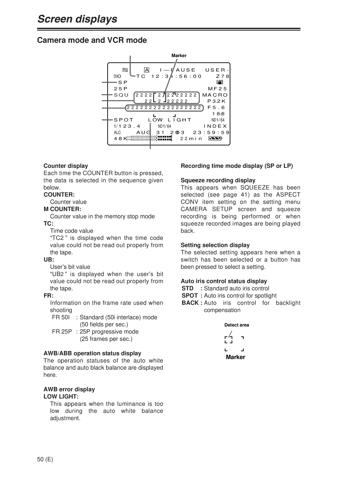
1Counter display
Each time the COUNTER button is pressed, the data is selected in the sequence given below.
COUNTER: Counter value
M COUNTER:
Counter value in the memory stop mode
TC:
Time code value
“TC2” is displayed when the time code value could not be read out properly from the tape.
UB:
User’s bit value
“UB2” is displayed when the user’s bit value could not be read out properly from the tape.
FR:
Information on the frame rate used when shooting
FR 50I : Standard (50i interlace) mode
(50 fields per sec.) FR 25P : 25P progressive mode
(25 frames per sec.)
2AWB/ABB operation status display
The operation statuses of the auto white balance and auto black balance are displayed here.
3AWB error display
LOW LIGHT:
This appears when the luminance is too low during the auto white balance adjustment.
4Recording time mode display (SP or LP)
5Squeeze recording display
This appears when SQUEEZE has been selected (see page 41) as the ASPECT CONV item setting on the setting menu CAMERA SETUP screen and squeeze recording is being performed or when squeeze recorded images are being played back.
6Setting selection display
The selected setting appears here when a switch has been selected or a button has been pressed to select a setting.
7Auto iris control status display
STD : Standard auto iris control
SPOT : Auto iris control for spotlight
BACK : Auto iris control for backlight compensation
Detect area
Marker
50 (E)
