Connecting the AQ-EC1 Extension Control Unit (Option)

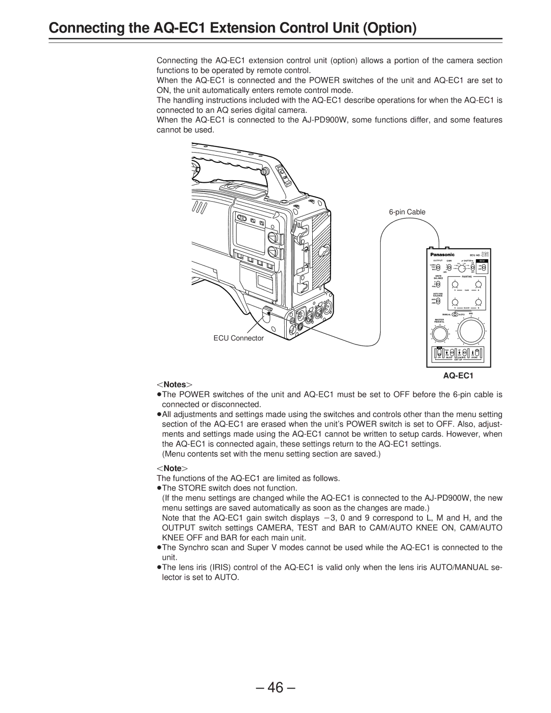
Connecting the AQ-EC1 extension control unit (option) allows a portion of the camera section functions to be operated by remote control.

When the AQ-EC1 is connected and the POWER switches of the unit and AQ-EC1 are set to ON, the unit automatically enters remote control mode.

The handling instructions included with the AQ-EC1 describe operations for when the AQ-EC1 is connected to an AQ series digital camera.

When the AQ-EC1 is connected to the AJ-PD900W, some functions differ, and some features cannot be used.

6-pin Cable

ECU Connector


ECU AQ -

O U T P U T

GAIN


SHUTTER

ECU

CAMERA

9


1/500

1/250


ON

1/1000


1/125

ON

TEST

0

1/2000


1/100


BAR

-3


OFF


(dB)


OFF

WHITE


PAINTING

BALANCE


A


B


PRE


R


GAIN

B

AUTO W/B


BALANCE


AWB


ABB


R


BLACK

B

MANUAL


AUTO

IRIS


MASTER


PEDESTAL


ON


PAGE


UP


ITEM


DWN


ON

OFF

SELECT


CONTROL


STORE


SET UP


AQ-EC1

Notes{

ÁThe POWER switches of the unit and AQ-EC1 must be set to OFF before the 6-pin cable is connected or disconnected.

ÁAll adjustments and settings made using the switches and controls other than the menu setting section of the AQ-EC1 are erased when the unit’s POWER switch is set to OFF. Also, adjust- ments and settings made using the AQ-EC1 cannot be written to setup cards. However, when the AQ-EC1 is connected again, these settings return to the AQ-EC1 settings.

(Menu contents set with the menu setting section are saved.)

Note{

The functions of the AQ-EC1 are limited as follows. ÁThe STORE switch does not function.

(If the menu settings are changed while the AQ-EC1 is connected to the AJ-PD900W, the new menu settings are saved automatically as soon as the changes are made.)

Note that the AQ-EC1 gain switch displays p3, 0 and 9 correspond to L, M and H, and the OUTPUT switch settings CAMERA, TEST and BAR to CAM/AUTO KNEE ON, CAM/AUTO KNEE OFF and BAR for each main unit.

ÁThe Synchro scan and Super V modes cannot be used while the AQ-EC1 is connected to the unit.

ÁThe lens iris (IRIS) control of the AQ-EC1 is valid only when the lens iris AUTO/MANUAL se- lector is set to AUTO.

– 46 –

Page 46
Image 46
Panasonic AJ-PD900WP operating instructions Connecting the AQ-EC1 Extension Control Unit Option, Pin Cable ECU Connector