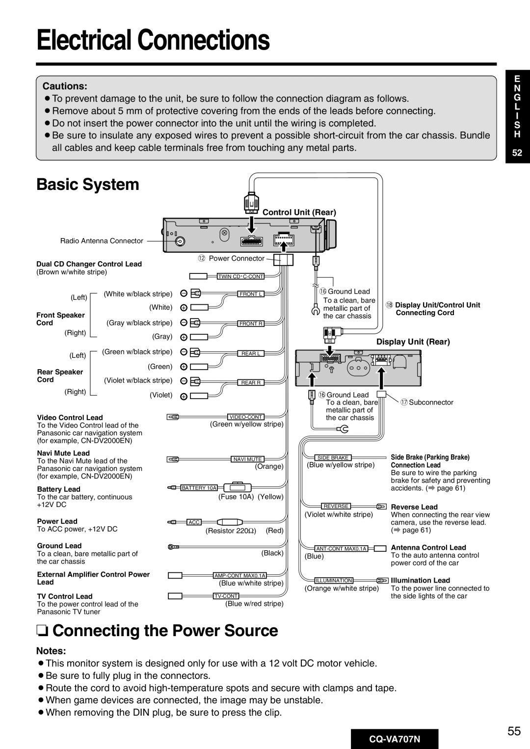
Electrical Connections
Cautions:
¡To prevent damage to the unit, be sure to follow the connection diagram as follows.
¡Remove about 5 mm of protective covering from the ends of the leads before connecting. ¡Do not insert the power connector into the unit until the wiring is completed.
¡Be sure to insulate any exposed wires to prevent a possible
E
N
G
L
I
S
H
52
Basic System
Control Unit (Rear)
Radio Antenna Connector
Dual CD Changer Control Lead (Brown w/white stripe)
!2Power Connector |
TWIN CD • |
(Left)
Front Speaker Cord
(Right)
(Left)
Rear Speaker Cord
(Right)
(White w/black stripe)
(White)
(Gray w/black stripe)
(Gray)
(Green w/black stripe)
(Green)
(Violet w/black stripe)
(Violet)
– | FRONT L |
+ |
|
– | FRONT R |
+ |
|
– | REAR L |
+ |
|
– | REAR R |
+ |
|
!6Ground Lead |
| |
To a clean, bare | !8Display Unit/Control Unit | |
metallic part of | Connecting Cord | |
the car chassis | ||
|
Display Unit (Rear)
!6Ground Lead |
|
|
To a clean, bare | !7Subconnector | |
metallic part of |
| |
Video Control Lead
To the Video Control lead of the Panasonic car navigation system (for example,
Navi Mute Lead
To the Navi Mute lead of the Panasonic car navigation system (for example,
Battery Lead
To the car battery, continuous +12V DC
Power Lead
To ACC power, +12V DC
Ground Lead
To a clean, bare metallic part of the car chassis
External Amplifier Control Power Lead
TV Control Lead
To the power control lead of the Panasonic TV tuner
(Green w/yellow stripe) |
NAVI MUTE |
(Orange) |
BATTERY 10A
(Fuse 10A) (Yellow)
ACC
(Resistor 220Ω) (Red)
(Black)
(Blue w/white stripe)
(Blue w/red stripe)
|
| the car chassis |
| |||||
|
|
|
|
|
| Side Brake (Parking Brake) | ||
| SIDE BRAKE |
|
|
|
| |||
(Blue w/yellow |
| stripe) | Connection Lead | |||||
|
|
|
|
|
|
|
| Be sure to wire the parking |
|
|
|
|
|
|
|
| brake for safety and preventing |
|
|
|
|
|
|
|
| accidents. (a page 61) |
|
|
|
|
| Reverse Lead | |||
|
| REVERSE |
|
| ||||
(Violet w/white stripe) | When connecting the rear view | |||||||
|
|
|
|
|
|
|
| camera, use the reverse lead. |
|
|
|
|
|
|
|
| (a page 61) |
|
|
|
|
|
|
|
| Antenna Control Lead |
|
|
| ||||||
(Blue) | To the auto antenna control | |||||||
|
|
|
|
|
|
|
| power cord of the car |
|
|
| Illumination Lead | |||||
| ILLUMINATION |
|
|
| ||||
(Orange w/white stripe) | To the power line connected to | |||||||
|
|
|
|
|
|
|
| the side lights of the car |
❏Connecting the Power Source
Notes:
¡This monitor system is designed only for use with a 12 volt DC motor vehicle. ¡Be sure to fully plug in the connectors.
¡Route the cord to avoid
¡When removing the DIN plug, be sure to press the clip.
55
