(6) Electric expansion valve
![]() When replacing the electric expansion valve and coil, be sure to attach the connectors in the correct positions. Labels are applied to the valve body and coil, corresponding to the connector colors, to identify them.
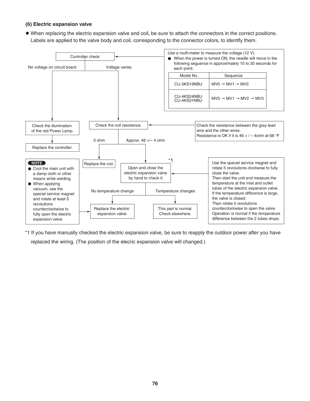
When replacing the electric expansion valve and coil, be sure to attach the connectors in the correct positions. Labels are applied to the valve body and coil, corresponding to the connector colors, to identify them.
Controller check
|
|
|
|
|
|
No voltage on circuit board | Voltage varies | ||||
|
|
|
|
|
|
|
|
|
|
|
|
|
|
|
|
|
|
Use a
When the power is turned ON, the needle will move in the following seguence in approximately 10 to 20 seconds for each point.
Model No. |
|
| Sequence | |||||
| MV0 |
| MV1 |
|
| MV2 | ||
|
| |||||||
|
|
|
|
|
|
|
|
|
| MV0 |
| MV1 |
|
| MV2 |
| MV3 |
|
|
|
|
| ||||
|
|
|
|
|
|
|
| |
|
|
|
|
|
|
|
|
|
Check the illumination of the red Power Lamp.
Replace the controller.
NOTE
Cool the main unit with a damp cloth or other means while welding. When applying vacuum, use the special service magnet and rotate at least 5 revolutions counterclockwise to fully open the electric expansion valve.
Check the coil resistance. |
|
| Check the resistance between the gray lead | |||
|
| |||||
|
|
|
|
|
| wire and the other wires. |
|
|
|
|
|
| |
|
|
|
|
|
| Resistance is OK if it is 46 + / – 4ohm at 68 °F |
0 ohm | Approx. 46 +/– 4 ohm |
| ||||
| ||||||
|
|
|
|
|
|
|
|
|
|
|
|
|
|
|
|
|
|
|
|
| *1 |
|
|
| Use the special service magnet and | |||
| Replace the coil. |
|
|
|
|
| ||||||||
|
| Open and close the |
|
|
|
| ||||||||
|
|
|
|
|
|
|
|
| rotate 5 revolutions clockwise to fully | |||||
|
|
|
|
| ||||||||||
|
|
|
|
|
| electric expansion valve |
|
|
|
| close the valve. | |||
|
|
| ||||||||||||
|
|
|
|
|
| by hand to check it. |
|
|
| Then start the unit and measure the | ||||
|
|
|
|
|
|
|
|
|
|
|
|
|
| temperature at the inlet and outlet |
|
|
|
|
|
|
|
|
|
|
|
|
|
| |
|
|
| No temperature change |
|
| Temperature changes | tubes of the electric expansion valve. | |||||||
|
|
|
|
| If the temperature difference is large, | |||||||||
|
|
|
|
|
|
|
|
|
|
|
|
|
| |
|
|
|
|
|
|
|
|
|
|
|
|
|
| the valve is closed. |
|
|
|
|
|
|
|
|
|
|
|
|
|
| Then rotate 5 revolutions |
|
|
| Replace the electric |
|
| This part is normal. |
| counterclockwise to open the valve. | ||||||
|
|
| expansion valve. |
|
| Check elsewhere. |
| Operation is normal if the temperature | ||||||
|
| |||||||||||||
|
|
|
|
|
|
|
|
|
|
|
|
|
| difference between the 2 tubes drops. |
|
|
|
|
|
|
|
|
|
|
|
|
|
| |
|
|
|
|
|
|
|
|
|
|
|
|
|
|
|
*1 If you have manually checked the electric expansion valve, be sure to reapply the outdoor power after you have replaced the wiring. (The position of the elecric expansion valve will changed.)
76