STEP 1 Antenna and television connections
Preparation
≥Refer to the television’s operating instructions.
≥Turn the television off and disconnect its AC power sup- ply cord.
To enjoy sound through other audio equipment (➜ page 59)
To enjoy progressive video
Connect to the component video (480P) input terminals on a television compatible with this unit’s copy guard sys- tem. (Video will not be displayed correctly if connected to an incompatible television.)
≥All Panasonic televisions that have 480P input terminals are compatible. Consult the manufacturer if you have another brand of television.
Setup precautions
≥Do not place in an enclosed area so the rear cooling fan and the cooling vents on the side are covered up.
≥Place the unit on a surface that is flat and not subject to vibration or impact.
≥Place in an area where condensation does not occur.
Condensation is a phenomenon where moisture forms on a cold surface when there is an extreme change in temperature. Condensation may cause internal damage to the unit.
➜In the following situation, with the power off, let the unit adjust to the room temperature and wait
Conditions where condensation may occur
Setting up
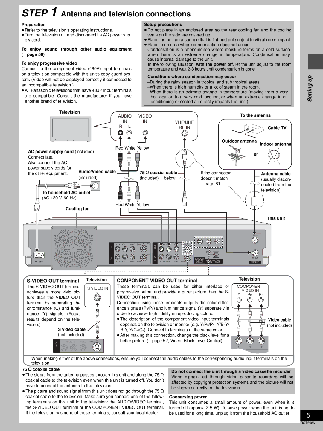
Television | VIDEO |
| |
| AUDIO |
| |
| IN | IN | VHF/UHF |
| R L |
| RF IN |
| Red White Yellow |
| |
AC power supply cord (included) |
|
| |
Connect last. |
|
|
|
Also connect the AC |
|
|
|
power supply cords for | Audio/Video cable | 75 ≠ coaxial cable | |
the other equipment. | |||
| (included) | (included) ➜ below | |
To household AC outlet
(AC 120 V, 60 Hz)
Red White Yellow
Cooling fan
To the antenna
| Cable TV |
Outdoor antenna | Indoor antenna |
or |
|
If the connector | Antenna cable |
doesn’t match | (usually discon- |
➜ page 61 | nected from the |
| television). |
This unit
RF IN
R - AUDIO - L | VIDEO | (L1) | AUDIO - L | VIDEO |
|
| ||
IN1 |
|
|
| OUT |
| Y | PB | PR |
|
|
|
|
|
| |||
|
|
|
| 1 |
|
| OPTICAL |
|
|
|
|
|
|
|
|
| |
|
|
| (L3) |
|
|
|
|
|
|
| IN3 |
|
| OUT2 |
|
| COMPONENT |
|
| RF OUT |
|
|
| R - AUDIO - L | VIDEO | R - AUDIO - L | VIDEO | VIDEO OUT | DIGITAL AUDIO OUT |
| VHF/UHF | |||
|
|
|
| (480P/480I) | (PCM/BITSTREAM) |
| ||||||
|
| Television | COMPONENT VIDEO OUT terminal |
| Television | |||||||
The | S VIDEO IN | These | terminals can | be | used for | either | interlace or | COMPONENT | ||||
achieves a more vivid pic- | progressive output and provide a purer picture than the S- |
| VIDEO IN |
| ||||||||
| Y | PR | ||||||||||
ture than the VIDEO OUT |
| VIDEO OUT terminal. |
|
|
|
| PB | |||||
|
|
|
|
|
|
|
| |||||
terminal by separating the |
| Connection using these terminals outputs the color differ- |
|
|
| |||||||
chrominance (C) and lumi- |
| ence signals (PB/PR) and luminance signal (Y) separately in |
|
|
| |||||||
nance (Y) signals. (Actual |
| order to achieve high fidelity in reproducing colors. |
|
|
| |||||||
results depend on the tele- |
| ≥The description of the component video input terminals |
|
| Video cable | |||||||
vision.) |
|
| depends on the television or monitor (e.g. Y/PB/PR, |
|
| (not included) | ||||||
S video cable |
|
|
|
| ||||||||
(not included) |
| ≥After making this connection, change the black level for a |
|
|
| |||||||
R - AUDIO - L | VIDEO | better picture (➜ page 52, |
|
|
| |||||||
OUT |
|
|
|
|
|
|
|
|
| Y | PB | PR |
1 |
|
|
|
|
|
|
|
|
|
|
|
|
|
|
|
|
|
|
|
|
|
|
| OPTICAL |
|
When making either of the above connections, ensure you connect the audio cables to the corresponding audio input terminals on the television.
75 ≠ coaxial cable
≥The signal from the antenna passes through this unit and along the 75 ≠ coaxial cable to the television even when this unit is turned off. You don’t have to connect the antenna to the television.
≥The picture and sound signal from this unit does not go through the 75 ≠ coaxial cable to the television. Make sure you connect one of the follow- ing terminals on this unit to the television: the AUDIO/VIDEO terminal, the
Do not connect the unit through a video cassette recorder
Video signals fed through video cassette recorders will be affected by copyright protection systems and the picture will not be shown correctly on the television.
Conserving power
This unit consumes a small amount of power, even when it is turned off (approx. 3.5 W). To save power when the unit is not to be used for a long time, unplug it from the household AC outlet.
5
RQT6986