Example
RQT8857-B
Region number supported by this unit
Features
Linked timer recordings with external equipment
Just one cord and simple connection with Hdmi terminal
You can easily select and play recorded programmes
Accessories
How to replace the fuse
Sales and Support Information
Before use
Table of Contents
Quick Start Guide
Remote Control Information
Using the remote control
About batteries
Quick
Main Unit
Remote Control
Location of Parts/Controls
Common to DVD/VHS
Unit’s Display
Rear Panel
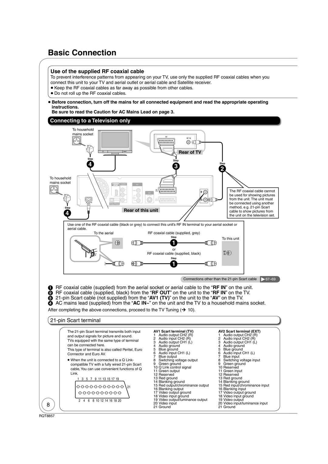
Connecting to a Television only
Basic Connection
Use of the supplied RF coaxial cable
Pin Scart terminal
Using a fully wired 21-pin Scart cable
Rear of satellite receiver
To view satellite programmes
To record satellite programmes
Setting the Channels and Clock
Power Save Function , to select On or Off then OK
To turn the unit on
Tips
, to change the setting
Clock Setting
to select Yes, then OK
, to select the item you want to change
Watching Television
, to select the current programme, then OK
To select desired channel
To directly enter Channels
Stopping Play Pausing Play
Playback
To select the VHS drive
Insert a cassette. ¼
To select the recording mode
Pausing Recording
Recording Television Programmes
To start recording
Timer Recording
To cancel a timer recording programming
, , to select the future programme, then OK
To check programmes ¼
Copying Titles
Seconds
− or −
To copy without fi nalising
When you start copying from the selected title
Copying Titles DVD ¼VHS
Deleting Titles
To select the DVD drive
, to select Delete, then
to select Delete, then OK
Disc must be finalised after recording or copying ¼
Important Notes for Recording
Broadcast in multi-channel sound
VHS Recording Modes and Durations
Advanced Recording
DVD Recording Modes and Durations
Repeatedly until the desired time is reached
To start fi nalising. or
Nalising
To select the DVD or VHS
, to select To Others then
Flexible Rec
Then OK
, , , to select Start, then OK
Recording from a Satellite Receiver
Satellite receiver you have connected
Select to select the DVD or VHS Drive
Manual Recording
Recording from an External Device
When DV Auto Rec screen does not appear
to select Rec to DVD, then to select Rec, then OK
Recording from a DV Camcorder
DV Auto Rec
Advanced Timer Recording
Manual timer recordings
To exit the timer recording list
Programme ¼ right, Tips
To cancel a timer recording in progress
to select Stop Recording, then OK
, to select the programme
While the unit is on
Timer Recording screen icons
To delete
To modify the programme , ,,to make changes, then OK
Check, Change, or Delete Programmes
Make timer programming on the TV
Making timer recordings on the television
To turn the unit off
Start and end of recording is controlled by TV
TV Guide
What is TV Guide?
Using the TV Guide
Yellow to display the list
Programme type
Blue to display the list
Categories
Advanced Disc Playback
, , , to select an item, then
, , , to select the title you want to watch, then OK
Press and hold
, to select the time, then
Playing Still Pictures Jpeg
, , , to select a picture, then OK
, to select the desired folder, then OK
, , , to select Folder
, to select Rotate Right or Rotate LEFT, then OK
, to select Zoom in, then OK
Rotate Pictures Picture Properties
Zoom
Using the Tree Screen to Find a Group
Playing MP3s
, to select a track, then OK to play
while a track is highlighted to display the tree screen
Advanced Video Cassette Playback
To fast-forward the tape
To rewind the tape
Press and hold for about 2 seconds
Press and hold for about 5 or more seconds
Press and hold until the picture noise disappears
Simultaneously
Press and hold until the shaking stops
To display on-screen indicators
Changing Audio during Playback On-screen Display Indicators
To exit on-screen indicators
Audio changes as follows
Information Messages
Status to show the screen information
To show the Digital Text
To show subtitles
New Service Message
Function Menu Window
Status Keep pressing to cycle through available displays
, to select a menu item, then OK
When the TV is on
When the TV is off
Power on link
Easy playback
Easy control only with Viera remote control
Using the Control
Select an item, then OK
Panel
Titles-Editing
Accessing the Title View
Entering Text
Title Operations
Change Thumbnail
Divide Title
Chapter Operations
Accessing the Chapter View
Chapters-Creating, Editing
Accessing the Playlist View
Creating, Editing and Playing Playlists
Creating Playlists
Editing Playlists/Chapters
Edit
Chapter View
Press Exit
You can go back to the Playlist View
Copying Titles Advanced
Register titles and playlists for copy
On the next
Copying list icons and functions
Cancel all registered copying setting and lists
Edit the copying list
DVD-V VHS
Press , to select Start Copying, then press OK
Setting On-Screen Display
Accessing the On-Screen Display
Menu Setting
Disc Menu
Other Menu
Play Menu Sound Menu
Picture Menu
Accessing the Management Menus
DVD Management
Message appears when finalising is finished
The first layer cannot be closed when there is no
Finalising
Create Top Menu
Setup Menu
Channel Settings
Accessing the Setup Menu
Tuning
Auto-Setup Restart
Add New DVB Services
DVB Manual Tuning
Signal Condition
Playback/Recording Settings
Picture Settings
Disc
Picture
Sound Settings
Sound
Connection
Display and Connection Settings
Display
Hdmi Settings1
AV2 Settings
TV System
Hdmi Video Format2
VHS and System Settings
Others
Child Lock
Other Settings
Using the Unit’s Remote Control to Operate the TV
Additional Connections
DVD output and DVD/VHS output
DVD/VHS common out
DVD priority out
Using an Audio/Video Cable
Using Component Video Cables
Red White Yellow
If you have a regular television CRT cathode ray tube
Using an Audio Cable for Better Sound
Using an Optical Digital Audio Cable for Better Sound
Rear of Amplifier or System Component
Red White
Regarding Viera Link Hdavi ControlTM function
Connecting to a TV
Connecting to a TV and a Receiver
Can do, Cannot do
Disc Handling
Usable Discs for Recording and Playback
Play-only Discs
Discs that Cannot be Played
Types of disc for the type of connected TV
1 PAL60
Inserting Discs
Disc Care
Still Picture JPEG2 Information
MP3s and Still Pictures Jpeg
MP3 File Information
Video Cassette Handling
To eject
Inserting a Video Cassette
Video Cassette Information
Troubleshooting Guide
To Reset This Unit
To reset the unit’s settings
To reset the ratings level settings
General Issues
Power
Following does not indicate a problem with the unit
Display is dim Change FL Display in the Setup menu
Operation
Connecting the unit
TV Guide
Viera Link
DVB-T
Playback Issues
Picture
Sound
TV. Using , return to the beginning of the title
Cover
Check the Sqpb setting
VHS Picture
VHS Sound
VHS Play
Recording Issues
Recording/Timer Recording/Copying/External input
VHS Recording
Editing Issues
Language code list
Discs
Frequently Asked Questions
Setup
Recording
TV Guide
Stands for a number Code on the remote control
The unit is performing a software update
Messages
On the Unit’s Display
On the TV
Hold
Unit Care
Cleaning the video heads
To clean this unit, wipe with a soft, dry cloth
Glossary
Safety Precautions
Specifications
UHF
This Unit is Intended for USE in Moderate Climates
For business users in the European Union
Index
RQT8857-B