Name and function of parts
IN |
| OUT |
|
|
|
|
REMOTE 1 |
|
| REMOTE 2 | |||
|
| VIDEO | OUT |
|
| |
| IN |
| R/PR | |||
|
|
|
|
|
|
|
|
|
|
|
|
|
|
|
|
|
|
|
|
|
|
|
| |||||
|
| ||||||
|
|
| IN |
|
| OUT | SERIAL |
|
|
| RGB 1 IN |
|
|
| RGB 2 IN / RGB 1 OUT |
G/Y | B/PB SYNC/HD | VD |
| ||||
![]()
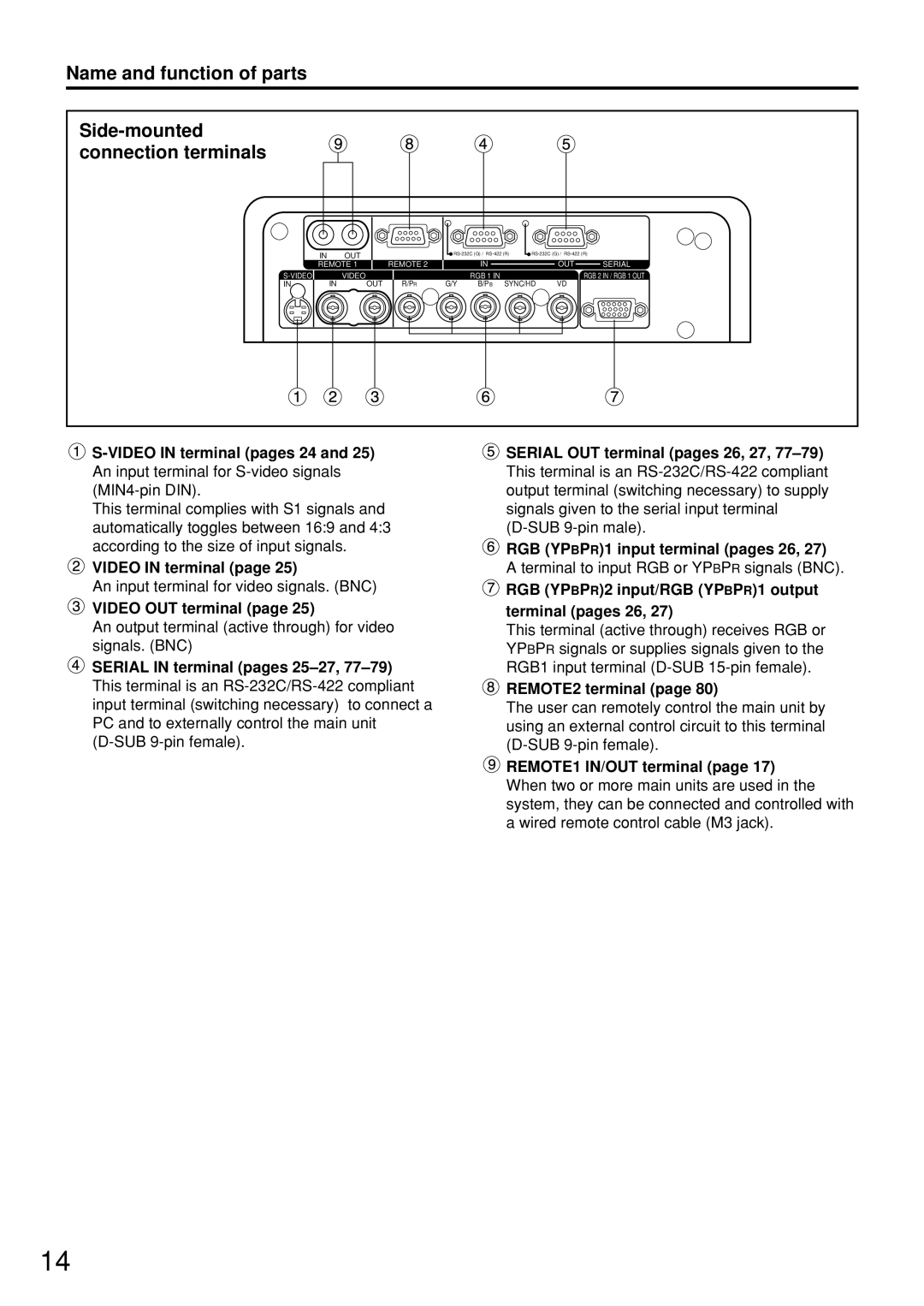
This terminal complies with S1 signals and automatically toggles between 16:9 and 4:3 according to the size of input signals.
VIDEO IN terminal (page 25)
An input terminal for video signals. (BNC)
VIDEO OUT terminal (page 25)
An output terminal (active through) for video signals. (BNC)
SERIAL IN terminal (pages
![]() SERIAL OUT terminal (pages 26, 27,
SERIAL OUT terminal (pages 26, 27,
![]() RGB (YPBPR)1 input terminal (pages 26, 27)
RGB (YPBPR)1 input terminal (pages 26, 27)
A terminal to input RGB or YPBPR signals (BNC).
 RGB (YPBPR)2 input/RGB (YPBPR)1 output terminal (pages 26, 27)
This terminal (active through) receives RGB or YPBPR signals or supplies signals given to the RGB1 input terminal
 REMOTE2 terminal (page 80)
The user can remotely control the main unit by using an external control circuit to this terminal
![]() REMOTE1 lN/OUT terminal (page 17) When two or more main units are used in the system, they can be connected and controlled with a wired remote control cable (M3 jack).
REMOTE1 lN/OUT terminal (page 17) When two or more main units are used in the system, they can be connected and controlled with a wired remote control cable (M3 jack).
14