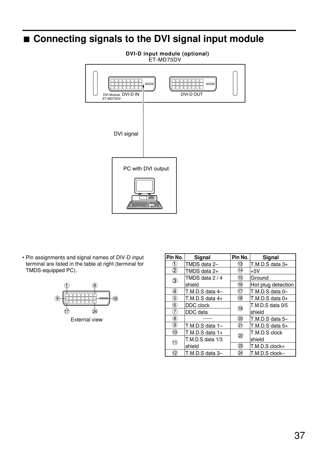
 Connecting signals to the DVI signal input module
DVI-D input module (optional)
ET-MD75DV
|
|
|
|
|
|
|
|
|
DVI Module |
|
| ||||||
|
|
|
|
|
|
| ||
|
|
|
|
|
|
|
|
|
DVI signal
PC with DVI output
•Pin assignments and signal names of
External view
Pin No. | Signal | Pin No. | Signal |
| TMDS data 2– |
| T.M.D.S data 3+ |
| TMDS data 2+ |
| +5V |
| TMDS data 2 / 4 |
| Ground |
| shield |
| Hot plug detection |
| T.M.D.S data 4– |
| T.M.D.S data 0– |
| T.M.D.S data 4+ |
| T.M.D.S data 0+ |
| DDC clock |
| T.M.D.S data 0/5 |
| DDC data |
| shield |
|
|
| T.M.D.S data 5– |
| T.M.D.S data 1– |
| T.M.D.S data 5+ |
| T.M.D.S data 1+ |
| T.M.D.S clock |
| T.M.D.S data 1/3 |
| shield |
| shield |
| T.M.D.S clock+ |
| T.M.D.S data 3– |
| T.M.D.S clock– |
37
