Service Adjustments and Calibrations |
ELECTRICAL INSPECTIONS
REQUIRED EQUIPMENTS / CONNECTIONS:
Voltmeter 150VDC: between C809 (+) and Ground
RMS Voltmeter: CRT Heater Terminal.
PROCEDURE:
1.Apply a PHILIPS pattern.
2.Adjust AC supply to 110 or 220 V. Adjust BRIGHT and CONTRAST control until get a totally black screen. The DC Voltmeter must be 130V±2.5V.
3.The heater terminal voltage must be:
DEFLECTION CIRCUIT PRE-ADJUSTEMENTS
REQUIRED EQUIPMENTS / CONNECTIONS: Voltmeter (50KV): Connect between CRT anode and CRT DAG GROUND.
PROCEDURE:
1.Apply a PHILIPS pattern.
2.Adjust VERTICAL HEIGHT (DAC B:5) until get a circle.
3.Apply a CROSSHATCH pattern.
4.Adjust BRIGHT and CONTRAST control until get a totally black screen. The voltage on Voltmeter must be:
5.Apply a PHILIPS pattern and readjust the BRIGHT and CONTRAST control to get a correct image picture.
6.Adjust the HORIZONTAL CENTER (“Cc” register) until the image is correctly centered.
To
7.Confirm that the horizontal width is in normal range.
8.Correct
9.Correct the horizontal width by adjusting R760 in the
AGC CIRCUIT PRE-ADJUSTMENTS
REQUIRED EQUIPMENTS / CONNECTIONS:
Oscilloscope: TP2.
PROCEDURE:
1.Apply a 63dB±2dB pattern signal (75Ω open) (Using a high VHF channel 7 ~ 13).
2.Set the CONTRAST control on center position.
3.Verify the CONTRAST variation with
Excluding the eraser part
WHITE BALANCE ADJUSTMENTS
REQUIRED EQUIPMENTS / CONNECTIONS: Oscilloscope: Connect to CRT board “GK” and ground.
PREPARATION:
1.Get turn ON the equipment for about 15 minutes.
2.Set standard WHITE BALANCE.
3.Adjust the image mode to “DYNAMIC”.
4.Fix the COLOR adjust in “NORMAL”.
5.Fix the CONTRAST adjust in “NORMAL”.
6.Enter in the service mode.
7.Adjust CUT OFF and DRIVE DATA to:
C0: CUT OFF_R= 0_64
C1: CUT OFF_G= 0_128
C2: CUT OFF_B= 0_64
C3: DRIVER_R= 64
C4: DRIVER_B= 64
8.Adjust SCREEN VR to minimum.
9.Connect the oscilloscope.
PROCEDURE:
1.In Service Mode, press
2.Look (GK) on the oscilloscope, then adjust
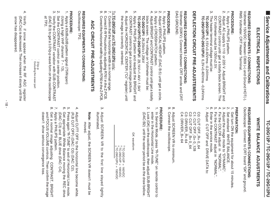
GK waveform
3.Adjust SCREEN VR to the first line stayed lightly illuminated.
Note: After adjust, the SCREEN VR doesn’t must be moved.
4.Adjust CUTT OFF to the horizontal line become white. (R,B CUT OFF) (DAC: C0) (DAC: C2).
5.Press again
6.Get appropriate White Balance moving the REC drive (DAC: C3) and BLUE drive (DAC: C4).
7.Apply a PHILIPS pattern.
8.Get a normal image adjusting CONTRAST, BRIGHT and FOCUS VOLUME controls. Then confirm the image doesn’t show serious convergence loss.
4.Verify if snow appear when the RF AGC register (DAC:Ca) is decreased. Then increase it slowly until the snow has disappeared.
-18 -