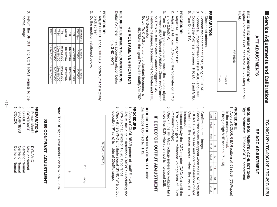
Service Adjustments and Calibrations | |
AFT ADJUSTMENTS | RF AGC ADJUSTMENT |
REQUIRED EQUIPMENTS / CONNECTIONS:
Digital Voltmeter, C.W. generator (45.75 Mhz) and VIF HEAD.
VIF HEAD
Tuner IF
Tuner
PREPARATION:
1.Disconnect antenna.
2.Connect the generator at TP37, using VIF HEAD.
3.Connect a jumper between TP8 (RF AGC) and GND.
4.Connect the Voltmeter between TP16 (AFT) and GND.
5.Turn On the TV.
PROCEDURE:
1.Adjust AFT (DAC: C9) to “128”.
2.Adjust the AFT coil (L167) until the Voltmeter on TP16 show 2.5±0.1V.
3.Turn On the generator, and move the output signal between 45,650Mhz and 45,850Mhz. Check the Voltmeter on TP16 must be indicate a variation biggest 0.4V.
4.Remove the jumper, disconnect the Voltmeter and THE CW Generator.
Note: To C.W.Generator the standard frequency is 45,75Mhz, the signal TV level is 90dBµV to 75O.
+B VOLTAGE VERIFICATION
REQUIRED EQUIPMENTS / CONNECTIONS: Digital Voltmeter (+): according relation below.
(_): GND (HOT)
PROCEDURE:
1.Adjust BRIGHT and CONTRAST control until get a totally black screen.
2.Do the medition relationed below:
VOLTMETER (+) | 20 inches | 29 inches |
|
|
|
C865(+) | 130VDC | 130VDC |
|
|
|
TP29 | 24V±2VDC | 27,4V±2VDC |
|
|
|
TP30 | 13V±2VDC | 13V±2VDC |
C859(+) | 18V±2VDC | 18V±2VDC |
|
|
|
TP5 | 9V±0,5VDC | 9V±0,5VDC |
|
|
|
TP34 | 200±15VDC | 220±15VDC |
TP11 | 5±0,25VDC | 5±0,25VDC |
|
|
|
C861 | 12,5±0,5VDC | 12,5±0,5VDC |
|
|
|
3.Return the BRIGHT and CONTRAST adjusts to the normal image.
REQUIRED EQUIPMENTS / CONNECTIONS: Digital Voltmeter: TP8 the AGC Tuner terminal.
PROCEDURE: |
|
|
|
|
|
|
|
|
|
| ||||
1. | Apply a COLOUR BAR pattern of 63±2dB (75Ω open) | |||||||||||||
| in the antenna terminal. |
|
|
|
|
|
| |||||||
| (Using a high VHF channel | 7 ~ 13). |
|
|
|
| ||||||||
|
|
|
|
|
|
|
|
|
|
|
|
|
|
|
|
| CHANNEL | 7 |
| 8 |
| 9 |
| 10 | 11 | 12 |
| 13 |
|
|
|
|
|
|
|
|
|
|
|
|
|
|
|
|
|
| MHz | 175,25 |
| 181,25 |
| 187,25 |
| 193,25 | 199,25 | 205,25 |
| 211,25 |
|
|
|
|
|
|
|
|
|
|
|
|
|
| ||
2. | Confirm a normal image. |
|
|
|
|
|
| |||||||
3. | Check if the noises disappear when the RF AGC register | |||||||||||||
| (DCA:Ca) is decreased and note the reference voltage. | |||||||||||||
| Confirm if the noise appear when the register is | |||||||||||||
| increased. |
|
|
|
|
|
|
|
|
|
| |||
4. | Increase slowly the AGC register (DAC: Ca) until the | |||||||||||||
| TP8 voltage get a reference voltage less of | 0.2V | ||||||||||||
| (maximum voltage) |
|
|
|
|
|
|
|
| |||||
5. | Check if the RF AGC voltage (reference voltage) falls | |||||||||||||
| more then 0.3V when the input is increased 2dB. | |||||||||||||
IF DETECTOR OUTPUT ADJUSTMENT
REQUIRED EQUIPMENTS / CONNECTIONS: Oscilloscope: Connect to TP12.
PROCEDURE:
1.Apply a COLOURBAR pattern of 100IRE level.
2.Adjust the output detection (DAC:Ce) (including the SYNC signal) inside of 1.0 ±0.1Vpp range
3.Check if the SYNC amplitude signal (SYNC “S“ & output detection “P” ratio) is inside of 30±5% range.
S / (S+P) = 30%±5
P = | 1.0Vpp |
S
Note: The RF signal ratio modulation is 87.5% ~ 90%.
SUB-CONTRAST ADJUSTMENT
PREPARATION: |
| |
1. | Picture MenU | DYNAMIC |
2. | CONTRAST | Max. or Normal |
3. | BRIGHT | Center or Normal |
4. | SHARPNESS | Center or Normal |
5. | COLOR | Center or Normal |
- 19 -
