INSTALL CONTROLS AND TRIM
|
|
|
|
|
|
|
|
|
|
|
|
|
|
|
|
|
|
|
|
|
|
|
|
|
|
|
|
|
| ||
mm) 25 |
|
|
|
|
| ||
|
|
| |||||
|
|
| |||||
|
|
|
| ||||
C |
|
| D |
C |
|
A | B |
|
H
Normal Water Line
C
G
![]()
![]()
![]()
![]()
![]()
![]()
![]()
![]()
![]()
![]() C
C
A |
F |
J
36"(914 | |
|
(170 mm)
2" (51 mm)
3/4"![]() (19 mm)
(19 mm)
(327 mm)
| E |
| |
(1029 mm) |
|
| C |
Control Center Line
Feeder Closing Level (Mark on Casting)
Burner
Center Line on
D D
(105 mm)
(206 mm)
A ![]() B
B
Install 1" Blowoff Valve
Boiler Foundation
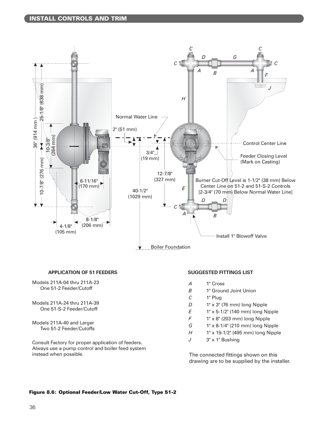
APPLICATION OF 51 FEEDERS
Models
One
Models
One
Models
Two
Consult Factory for proper application of feeders. Always use a pump control and boiler feed system instead when possible.
SUGGESTED FITTINGS LIST
A1" Cross
B1" Ground Joint Union
C1" Plug
D1" x 3" (76 mm) long Nipple
E1" x
F1" x 8" (203 mm) long Nipple
G1" x
H1" x
J3" x 1" Bushing
The connected fittings shown on this drawing are to be supplied by the installer.
Figure 8.6: Optional Feeder/Low Water Cut-Off, Type 51-2
36