8 Turn on the power. If the red LED lights, turn off the power and proceed to the next step. If the red LED does not light, refer to the Troubleshooting section.
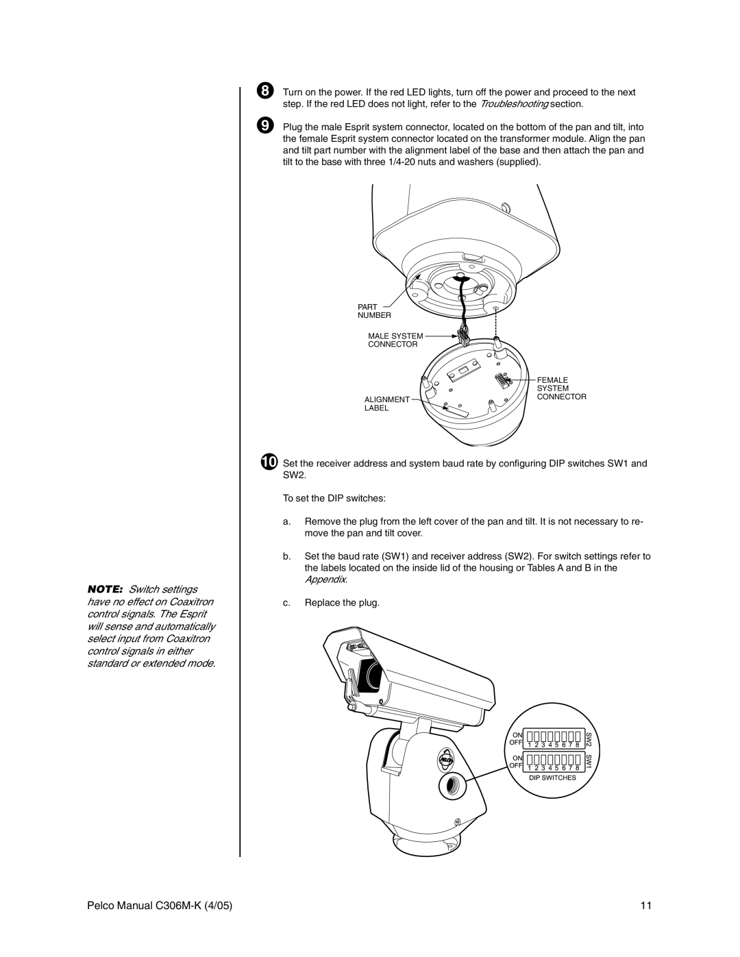
9 Plug the male Esprit system connector, located on the bottom of the pan and tilt, into the female Esprit system connector located on the transformer module. Align the pan and tilt part number with the alignment label of the base and then attach the pan and tilt to the base with three
PART
NUMBER
MALE SYSTEM ![]()
CONNECTOR
ALIGNMENT LABEL
![]() FEMALE SYSTEM CONNECTOR
FEMALE SYSTEM CONNECTOR
NOTE: Switch settings have no effect on Coaxitron control signals. The Esprit will sense and automatically select input from Coaxitron control signals in either standard or extended mode.
10 Set the receiver address and system baud rate by configuring DIP switches SW1 and SW2.
To set the DIP switches:
a.Remove the plug from the left cover of the pan and tilt. It is not necessary to re- move the pan and tilt cover.
b.Set the baud rate (SW1) and receiver address (SW2). For switch settings refer to the labels located on the inside lid of the housing or Tables A and B in the Appendix.
c.Replace the plug.
Pelco Manual | 11 |