USING PIP (BASIC CONNECTIONS)
at the same time (one main screen pic- ture and one small picture, or PIP). This TV has two separate inputs (ANT[enna] “A” and PIP ANT[enna] “B”) for your home’s Antenna and/or Cable TV system signals. ANT “A” is referred to on screen as
The ANT “A” input is primarily for the TV’ s main screen picture. The PIP ANT “B” input is provided as a second dedicated source option for the TV’s PIP “window” and its feature opera- tions. The signal connected to the PIP ANT “B” input can be either a split sig- nal input (as described and illustrated on this page) or a separate external sig- nal source (such as an additional home antenna, satellite dish system, or video accessory device).
See the following steps on how channels connected to the PIP ANT(enna) “B” input can be shown and used within the PIP window.
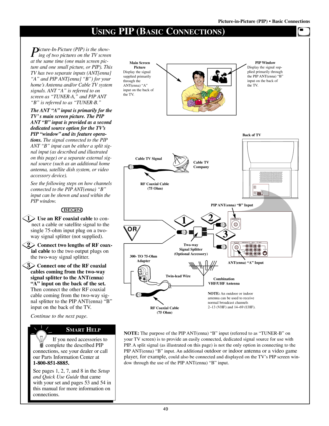
Main Screen
Picture
Display the signal supplied primarily through the ANT(enna) “A” input on the back of the TV.
Cable TV Signal
Cable TV
Company
RF Coaxial Cable
(75 Ohm)
PIP Window
Display the signal sup- plied primarily through the PIP ANT(enna) “B” input on the back of the TV.
Back of TV
BEGIN
![]() Use an RF coaxial cable to con- nect a cable or satellite signal to the single
Use an RF coaxial cable to con- nect a cable or satellite signal to the single
![]() Connect two lengths of RF coax- ial cable to the two output plugs on the
Connect two lengths of RF coax- ial cable to the two output plugs on the
![]() Connect one of the RF coaxial cables coming from the
Connect one of the RF coaxial cables coming from the
“A” input on the back of the set. Then connect the other RF coaxial cable coming from the
Continue to the next page.
SMART HELP
![]() If you need accessories to complete the described PIP
If you need accessories to complete the described PIP
connections, see your dealer or call our Parts Information Center at
See pages 1, 2, 7, and 8 in the Setup and Quick Use Guide that came with your set and pages 53 and 54 in this manual for more information on connections.
PIP ANT(enna) “B” Input
1 | 2 | PIP ANT "B" 75Ω |
|
OR |
| 3 |
|
|
|
| |
| ANT "A" 75Ω MONITOR OUT | AV1 IN AV2 IN | |
| VIDEO |
| |
Signal Splitter |
|
| Y |
|
| V | |
|
| MONO/L | |
(Optional Accessory) |
| AUDIO | Pb |
| R | Pr | |
300- TO |
|
|
|
Adapter |
| ANT(enna) “A” Input | |
|
| ||
Combination |
| ||
|
| ||
| VHF/UHF Antenna |
| |
| NOTE: An outdoor or indoor | ||
| antenna can be used to receive | ||
| normal broadcast channels |
| |
RF Coaxial Cable | |||
(75 Ohm) |
|
|
|
NOTE: The purpose of the PIP ANT(enna) “B” input (referred to as
49